Introduction
The scratch and rumble filtering circuit is essential to hi-fi amplifiers, but it is often overlooked in several designs. Even when present, the filter may be in the form of a weak 6dB per octave filter.
This article discusses a 12dB per octave scratch and rumble filter circuit that can be connected to the tape monitor or any comparable amplifier facility.
Hardware Required
| S.no | Components | Value | Qty |
|---|---|---|---|
| 1 | Transistor | 2N3904 | 1 |
| 2 | Polar Capacitor | 100u, 2u2, 10u | 1, 1, 1 |
| 3 | Non Polar Capacitor | 220, 2n, 470 | 2, 1, 1 |
| 4 | Resistor | 6K8, 82K, 27K, 4K7 | 1, 2, 2, 1 |
| 5 | Switch | – | 3 |
| 6 | Battery | 9V | 1 |
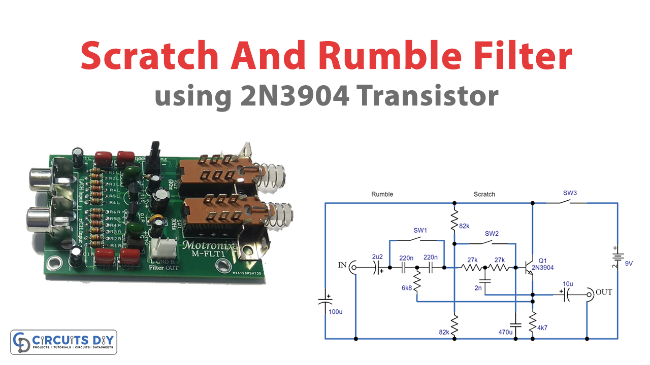
Circuit Diagram

Working Explanation
The passive high pass filter of the Scratch and Rumble Filter Circuit is made from the series capacitance of C3 and C4 and the parallel resistance of R2 and R3.
A passive filter of this kind has a very slow starting roll-off and a maximum attenuation rate of only 6 dB per octave. This is why a bootstrapping resistor is used to boost efficiency.
Depending on Q1, R1 strengthens the input signal at the output of the buffer amplifier above a cutoff frequency at which the gain of the circuit may otherwise fall fairly.
Because of losses caused by C4, the signal level at the emitter of Q1 is much lower than the level at the junction of C3 and C4 when the frequency is properly below the cutoff frequency. Because of this, a portion of the signal at the junction of C3 and C4 is tapped out by means of R1, and C3 and R1 effectively construct a second high-pass filter network.
This reduces the attenuation rate to a minimum of 12dB per octave, eliminating the smooth beginning roll-off rate (in fact, there exists a tiny and minor peak of roughly 0.5dB above a cutoff frequency).
The low pass filter operates similarly to the high pass filter, except that the R and C filter components must be switched around to get the desired filter action.
For situations when low pass filtering is necessary, SW1 may effectively be used to avoid the high pass filter components. The DC blocking at the input is then maintained by C2.
When just high-pass filtering is required, SW2 may be utilized to isolate the low-pass filter components.
With these specific component values, the rumbling filter’s response begins to go below unity at around 45Hz, reaches the -6 dB mark just above 30Hz, and then gradually decreases at a notional 12dB per octave.
The scratch filter’s response has a unity-gain crossover at around 6.5kHz, a -6dB crossover at about 10kHz, and a minimum 12dB per octave roll-off below 1kHz.
Conclusion
In conclusion, the scratch and rumble filter circuit is valuable to any hi-fi amplifier design. Its 12dB per octave filter and customizable options provide an efficient way to eliminate unwanted noise and distortion from your audio output.
We hope this article has provided valuable insights into this circuit’s workings and how we can implement it in your audio setup. If you have any questions or comments, please feel free to reach out to us. We appreciate your feedback and look forward to hearing from you.