Introduction
Creating a doorbell with a memory circuit is a fun and useful DIY project for those new to electronics. This doorbell not only alerts you with an LED light when someone is at your door, but it also remembers the last time it was activated and displays the date and time on an LCD screen. With this guide, you will learn how to build this handy device to enhance your daily life.
Are you prepared to construct this circuit, then? Here you will find all the information you need to build a doorbell memory circuit. Why wait any longer? Let’s get started on building your own doorbell memory circuit!
Hardware Required
You will require the following hardware for Doorbell With Memory Circuit.
| S.no | Component | Value | Qty |
|---|---|---|---|
| 1. | Transformer | 12v | 1 |
| 2. | Capacitor | 220uF / 25W | 1 |
| 3. | Resistor | 680, 10k, 68k, 100k, 470k | 1, 1, 2, 1, 1 |
| 4. | Transistor | BC547 | 2 |
| 5. | Diode | 1N4001, 1N4148 | 1, 1 |
| 6. | LED | – | 1 |
| 7. | Switch | – | 2 |
| 8. | Jumper Wire | – | 1 |
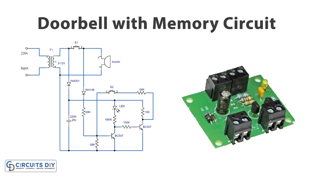
Circuit Diagram

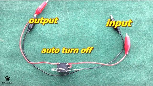
Testing
- Begin by connecting the circuit to a power source and ensuring the LED is off and the transistor T1 is turned off.
- Press the doorbell button, S1, and observe if the LED turns on and T1 is turned on.
- Verify if the LED remains on even when you release the button and if the transistor T1 stays on.
- Check if the circuit resets when you press the reset button S2, the LED turns off, and T1 turns off.
- Observe if the LED is illuminating outside the door or in the doorbell switch box.
Working Explanation
This Door Bell with a Memory circuit is designed to solve the problem of not knowing if someone has visited while you were not at home. The circuit is powered by the bell transformer and uses a diode, D1, and a capacitor, C1, to provide enough d.c. Voltage for the ‘memory’ function.
Normally, when no one is ringing the doorbell, transistor T1 turns off, and T2 runs, creating a latch for T1. This means that LED D3 will not be on in these conditions. However, when a visitor arrives and rings the doorbell, the circuit “jumps into action.” Through D2 and R1, the doorbell switch, S1, provides a base/drive current to T1, which turns off T2 and, as a result, switches on LED D3.
The transistor latch (T2) then switches the other way, and T1 is kept on by the current path to the positive supply through S2 (normally closed), R5, and R6. The visitor may leave disappointed, but the LED will indicate their previous presence. When you return, you can see the LED. You can then reset the circuit by simply depressing S2, which stops the base current path keeping T1 on, causing it to turn off. This turns off the LED and starts T2, resetting the latch.
Final Words
In this tutorial, we have covered building a doorbell with a memory circuit, including the materials needed, step-by-step instructions, and critical concepts to keep in mind. We hope you have found this tutorial informative and easy to follow. Ask any questions in the comment section, and we’ll try to answer. Happy learning!