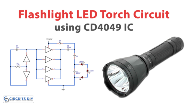
LEDs are used for various purposes in our daily lives. Most commonly in emergency lights, fancy lights, etc. These lights drive through an LED Driver Circuit. This article explains a simple 1W Led Driver Circuit. How an led driver circuit works and what are its uses?
We know about the power source requirement to light an LED. But, High power LEDs produce much amount of heat. Due to increased temperature, LED’s lifetime reduces when operating above its temperature range. This causes irreparable damage to the LEDs.
Therefore, LED Driver circuits are widely used. Drive circuit control and maintain the maximum forward current to the LED. It minimizes the extra current which dissipates as heat.
Hardware Components
The following components are required to make LED Driver Circuit
| S.No | Component | Value | Qty |
|---|---|---|---|
| 1. | Breadboard | – | 1 |
| 2. | Connecting Wires | – | 1 |
| 3. | Battery | 12v | 1 |
| 4. | Regulator IC | LM317 | 1 |
| 5. | LED | – | 1 |
| 6. | Resistor | 10 ohms | 1 |
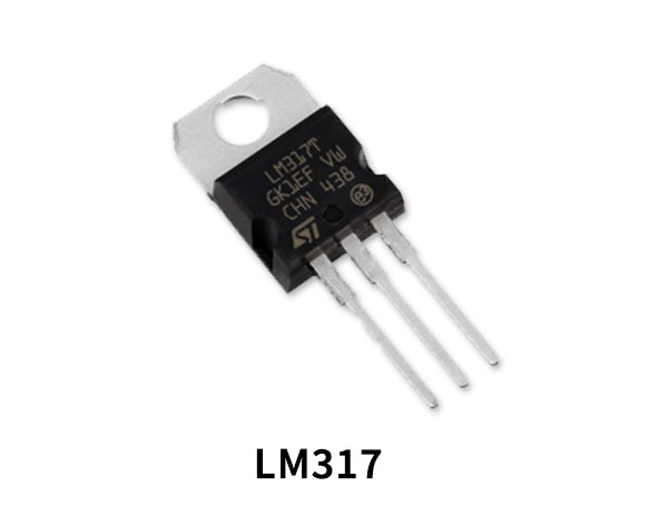
LM317 Pinout
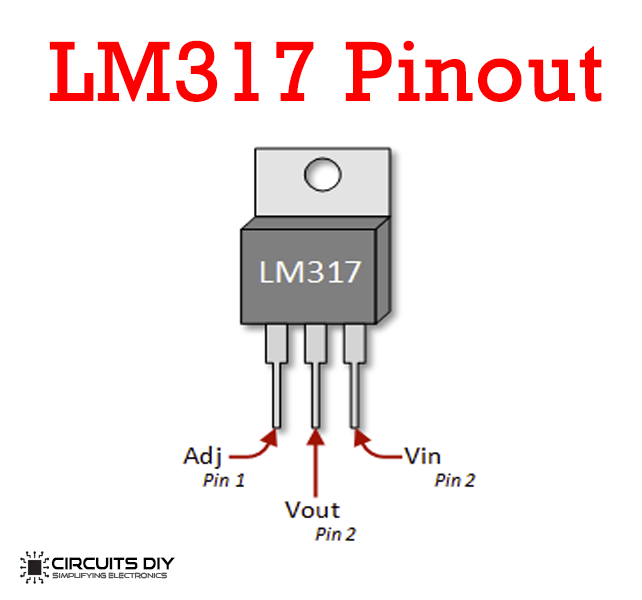
For a detailed description of pinout, dimension features, and specifications download the datasheet of LM317
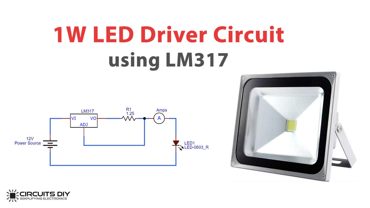
LED Driver Circuit
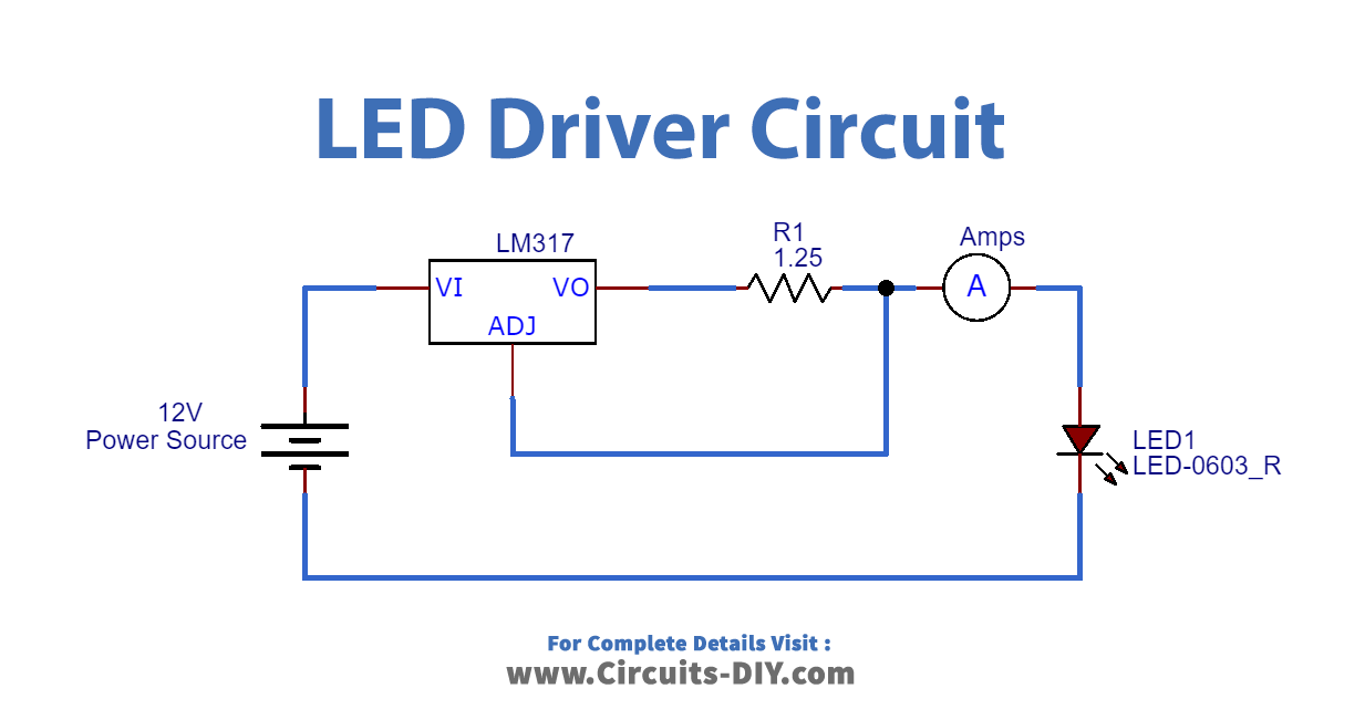
Working Explanation
In this Driver Circuit, we are using an LM317 IC. Generally, the LM317 IC is the current limiter. Here, when power supplies and current flow through the circuit, an LED glows. However, on the back end, LM317 IC acts as a current limiter and will limit the current. It only allows the maximum current to drive the LED only. In this way, this Circuit helps to prevent LEDs from overheating due to heat dissipation.
Advantages
- It is simple and cost-effective
- No need for a Transformer
- Small in size
Applications
- It has used infant and decorative lights
- Led has been used in cars, bikes, and various other automobiles
- It has usage in various domestic applications.
- This circuit can also be used in the combination with the doorbell to provide an indication.