Introduction
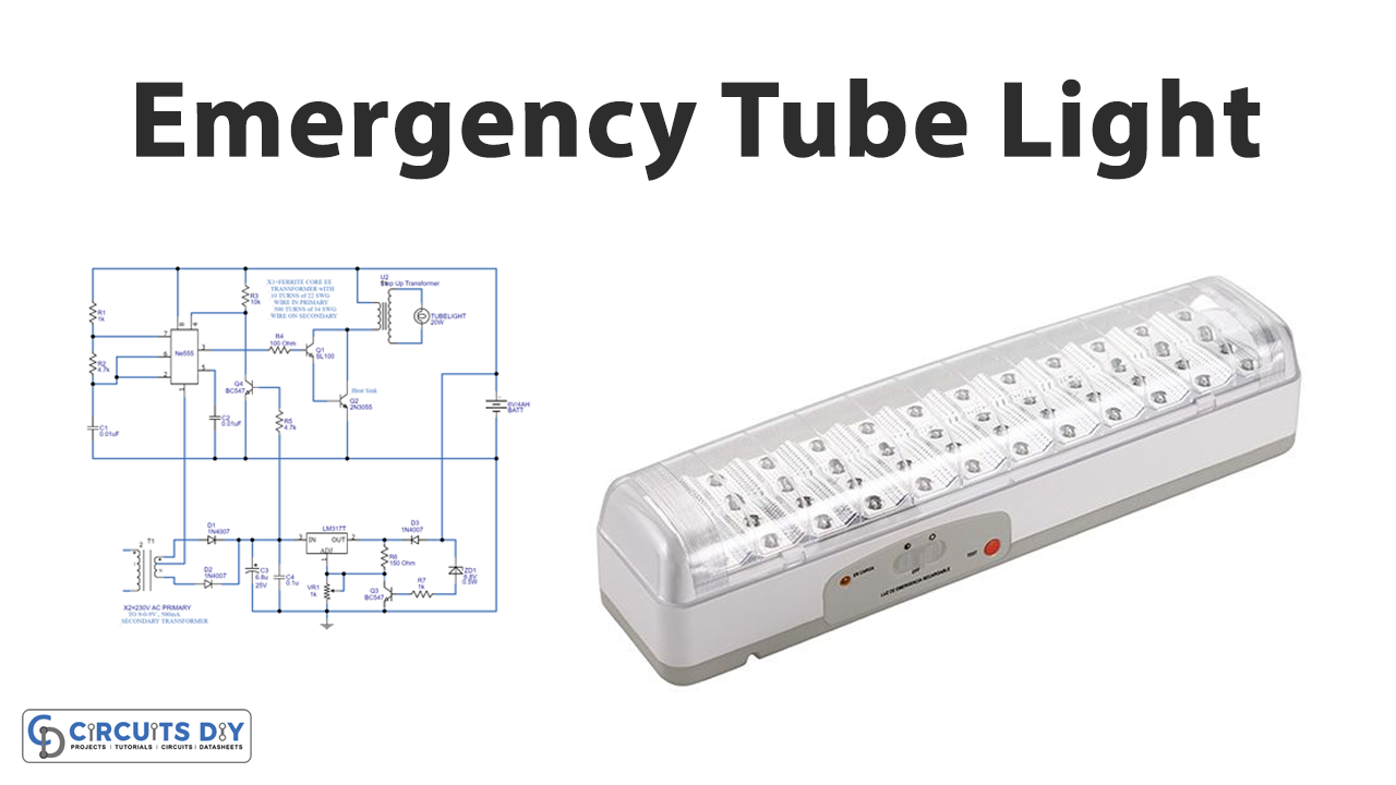
Emergency lighting is now a requirement in both business and residential buildings. Many building standards also mandate emergency lights to be installed as a replacement for older structures. Also, Emergency lighting is utilized in life-threatening circumstances, such as when the main power supply is cut off or when a typical electrical light goes out. As a result, a sudden power outage might result in a fire or a power outage. This lighting system is utilized in buildings and incorporates a battery that automatically turns on the light when the power goes off. These lights serve a critical function in providing protection for inhabitants during an emergency. In the event of a power outage, a battery-powered emergency light may be activated to visually instruct inhabitants how to safely exit the building. Many building standards also mandate emergency lights to be installed as a retrofit for older structures. So, in this tutorial, we are going to make a “Full Automatic emergency tube light circuit”.
Automatic emergency lighting is a simple to build a circuit that may be completed in a matter of minutes. The components for the Emergency Light circuit are easily accessible and inexpensive. It’s a good idea to employ it when it comes to energy conservation.

Hardware Components
The following components are required to make Emergency Tube Light Circuit
| S.no | Component | Value | Qty |
|---|---|---|---|
| 1. | Step down transformer | 9-0-9V | 1 |
| 2. | IC | NE555 Timer | 1 |
| 3. | Transistor | BC547, SL100 | 2 |
| 4. | Electrolytic Capacitor | 6.8uF | 1 |
| 5. | Transistor | 2N3055 | 1 |
| 6. | IC | LM317 | 1 |
| 7. | Diode | 1N4007 | 3 |
| 8. | Zener Diode | – | 1 |
| 9. | Potentiometer | 1K | 1 |
| 10. | Tube Light | – | 1 |
| 11. | Capacitor | 0.1uF, 0.01uF | 1,2,1 |
| 12. | Resistor | 1K, 4.7K, 10K, 150 Ohm | 2,2,1,1 |
555 IC Pinout

For a detailed description of pinout, dimension features, and specifications download the datasheet of 555 Timer
LM317 Pinout

For a detailed description of pinout, dimension features, and specifications download the datasheet of LM317
Emergency Tube Light Circuit
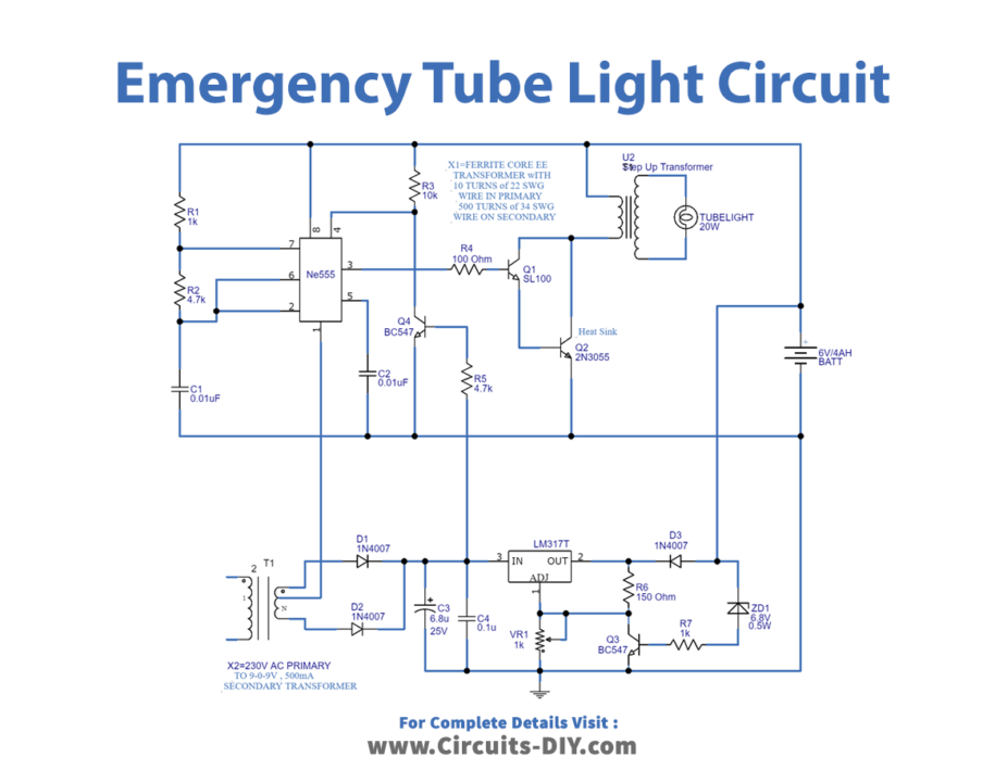
Working Explanation
In this Full Automatic emergency tube light circuit, we divide the circuit into two steps; the battery charger circuit and the 20 Watts tube light driver circuit.
The battery charger circuit comprises a center-tapped step-down transformer, two 1N4007 diodes that act as full-wave rectifiers, rectifying the step downed AC supply from the transformer. The variable voltage regulator IC LM317 then filtered and regulated the rectified DC, and it then gave a regulated constant DC supply to the 6 volt 4Ah battery. When the power supply is provided, the T4 transistor (BC547) divides the tube light driver circuit from the charger circuit.
We made the 20 Watt tube light driver circuit up of a timer IC555 and a step-up transformer X1. The primary winding of the step-up transformer X1 comprises 10 turns of 22SWG wire and 500 turns of 34SWG wire on the secondary, with a 20W tube light attached to the secondary of the X1. The primary of the X1 transformer is driven by a pulse from the timer IC 555, whose pulse duration is determined by the R1, R2, and C1 timing components.
Application and Uses
- One can use it in night lamps, street lights, etc.
- The circuit is useful where there are load shedding issues.
- Also, can be employed to avoid sudden power failures at workplaces.