Introduction
DC motors have a wide range of applications in electronic devices. If you’re an electrical or electronic student, then you must have learned its internal structure and worked with your teachers. If you’re a person who loves to make projects, then you must have used it in various projects. Or, If you’re a person who just researches industrial and other simple machinery, then you also must have seen it in different places. Because apparently, DC motors are in every other application. So, Controlling the speed of the DC motor Speed control is an important thing to discuss.
Different applications require different speeds but many of the applications need different speed levels. For example, robotic cars may not want the backward speed the same as the forward speed. In the same way, some industrial devices work at different levels of speed. So, in this tutorial, we are going to make and understand the working of the “DC Motor Speed Control PWM circuit”
Talking about PWM, the pulse width modulation is the square wave signals that switch between ON and OFF states. Pulse Width Modulation is primarily the method that is used to reduce the average power of an electrical signal. Hence, this circuit can control the brightness of LEDs. It also has various other applications in different electronic circuits. For example, it can control the speed of the motor. To generate the pulses there is a term called duty cycle is used. The duty cycle ratio of the time when the signal is high to the total time it gets to complete one cycle. Expressed in percentage
Features of L293D Motor Driver
- It has the wide Supply Voltage Range from 4.5V to 36V
- Moreover, it includes a Separate Input-Logic Supply.
- The driver also has Internal ESD Protection.
- It allows High Noise Immunity Input.
- Output Current: 600 mA
- Peak Output Current: 1.2 A
Hardware Required
| S.no | Component | Value | Qty |
|---|---|---|---|
| 1. | IC | NE555 Timer | 1 |
| 2. | IC | L293D | 1 |
| 3. | DC Motor | 1000 RPM | 1 |
| 4. | Potentiometer | 100KΩ | 1 |
| 5. | Diode | 1N4007 | 2 |
| 6. | Switch | – | 1 |
| 7. | Bread Board | – | 1 |
| 8. | Electrolysis Capacitor | 0.1μF | 1 |
| 9. | Ceramic Capacitor | 1μF | 1 |
| 10. | Resistor | 1KΩ,100Ω | 1, 2 |
| 11. | Connecting wires | – | – |
| 12. | Battery | 9v | 1 |
| 13. | 2-Pin Connector | – | 2 |
Circuit Diagram
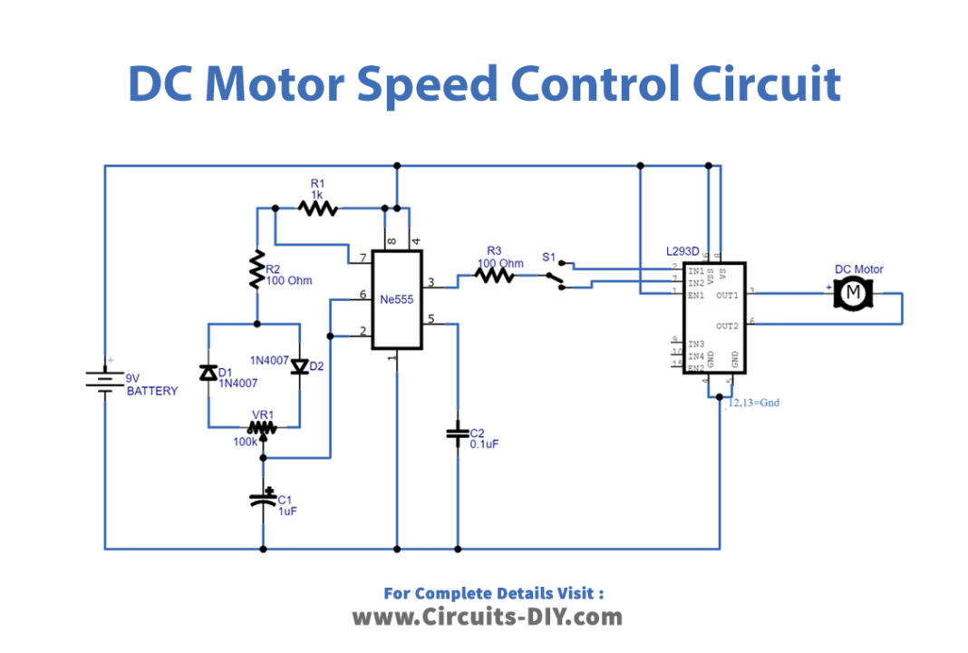
Working Explanation
In this DC Motor Speed Control PWM circuit timer, IC 555 is working as a square pulse generator depending on the value of the potentiometer. The output pulse width or duty cycle can get change and the output from IC 555 is immediately given to the motor driver H-Bridge IC (H bridge is a setup that is employed to drive or run motors both in the clockwise and anti-clockwise direction. Hence IC can run two motors at any direction at the same time) using a toggle switch. By using the toggle switch you can change the input of L293D. We connected the DC motor between out 1 and out 2 pins of the motor driver IC.
Application and Use
The circuit can be used to adjust the speed of the DC motor Of:
- Conveyor belts.
- DC fans.
- Robotic cars.
- In medical applications.
- Industrial applications.
- Automation circuits.
- In Robotics, etc