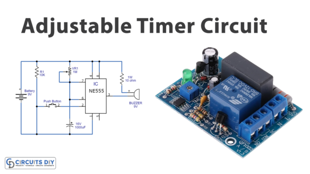
As the name proposes, “One-minute Timer,” this DIY circuit tutorial is a timer circuit that turns OFF and ON an LED exactly after every one minute. It employs a NE555 timer IC that is a timer itself. The NE555 timer IC is likewise utilized to generate an oscillating pulse.
It has the property to turn its Timer HIGH as long as For a minute, the timer output yield remains HIGH, and afterward, it turns down to LOW. Thus, this effect creates an oscillating effect.
Therefore, we can utilize 555 timers to make different clock circuits like short clock circuits, clock circuits, etc. Everything we require to change the estimation of Resistor R1 or potentially Capacitor C1. We have to set 555 IC in Monostable mode to manufacture Timer.

Hardware Components
The following components are required to make Timer Circuit
| S. no | Component | Value | Qty |
|---|---|---|---|
| 1 | IC | NE555 | 1 |
| 2 | Variable Resistor | 1M | 1 |
| 3 | Resistor | 10K | 1 |
| 4 | Capacitor | 1000uF | 1 |
| 5 | Switch | – | 1 |
| 6 | LED Diode | – | 1 |
NE555 IC Pinout

For a detailed description of pinout, dimension features, and specifications download the datasheet of 555 Timer
Timer Circuit
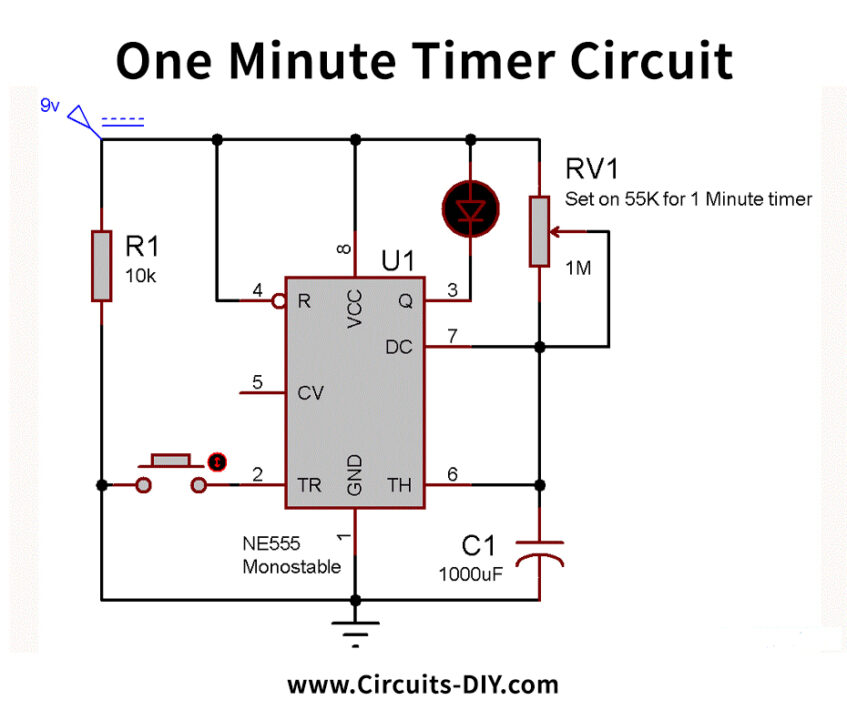
Working Explanation
The circuit operation of the One Minute Timer Circuit is simple. Before going into the process detail, note that we have utilized LED at reverse logic, which implies when OUTPUT pin 3 is low, LED will be ON, and when OUTPUT is HIGH at that point, LED will be OFF. Thus, we can determine the OFF time above, which implies after the determined time LED will be turned ON.
Moreover, the LED will be ON at first (OUTPUT PIN 3 LOW), when we press the button (trigger the 555 through TRIGGER PIN 2), the clock will begin, and the LED will get OFF (OUTPUT PIN 3 LOW) after the determined time term, PIN 3 will again turn out to be LOW and LED get turned ON.
Applications and Uses
The typical application of One Minute Timer IC is to generate the desired LED delays. However, it likewise uses a baud rate and a reference signal generator.