In this tutorial, we will show you how to make a Touch Switch Circuit using a 555 timer IC. The main component of this circuit is a 555 timer IC and we will use 2 pieces of wires as a switch. When we will touch both the wires together with our finger, the LED will turn on and it will turn off immediately when the finger is removed.
Using this circuit, you can also control AC or other high-load appliances by coupling the output of 555 timer IC to a relay. The maximum current output of this circuit is about 200mA. So you can connect any component that consumes less than 200mA, directly to the output of 555 timer IC.

Hardware Components
The following components are required to make the Touch Switch Circuit
| S. NO | Component | Value | Qty |
|---|---|---|---|
| 1. | Breadboard | – | 1 |
| 2. | Battery | 9v | 1 |
| 3. | Connecting Wires | – | 1 |
| 4. | IC | NE555 Timer | 1 |
| 5. | Capacitors | 10uF, 0.01uF | 1, 1 |
| 6. | Resistors | 100k, 470 ohm | 1, 1 |
| 7. | LED | 5mm | 1 |
555 IC Pinout

For a detailed description of pinout, dimension features, and specifications download the datasheet of 555 Timer
Circuit Diagram
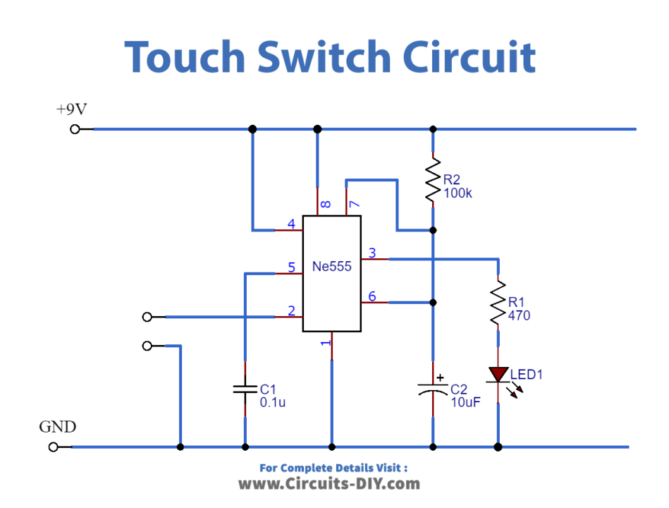
Connections
- Place the 555 timer IC on the breadboard.
- Connect Pin 8 and Pin 4 to VCC
- Connect Pin 1 to GND.
- Use a jumper wire to connect Pin 6 and Pin 7 together.
- Connect the 100K resistor from Pin 7 to VCC.
- Connect the 10uF capacitor from Pin 6 to GND.
- Use jumper wire as a touch switch by connecting one piece of wire to Pin 2 and connecting the second piece to GND.
- Use a 0.1uF capacitor to connect Pin 5 to GND
Working Explanation
In this circuit, 555 timer IC will operate in the monostable mode which means it will only have one stable state. Here the stable state is LOW, so the output of the 555 timer becomes LOW when the trigger is removed. The LED will be ON only for the time during which the trigger is present. The trigger pin of the 555 timer is very sensitive and it can merely be pulled high by human body potential. The capacitor between Pin 6 and Pin 1 determines the turn-on time of the LED, once a trigger is applied.
To make a touch plate, we can use two pieces of any conductor. In this circuit, we have used two pieces of jumper wires. One piece of the conductor should be connected to the trigger pin of 555 Timer and the other piece to the ground.
Application
- This circuit is suitable for making touch-operated bells.
- We can also use this circuit to make buzzers of small toys that operate for a small time and then switch off automatically.