Dc machines are widely used in various commercial and industrial sectors and so are Dc motors. And, in many places, the accurate speed of these machines is necessarily required. As you know that every industry uses mechanical machines where energy interchange or transform into another. For example, the electric motor converts electrical energy into mechanical. Hence, the speed of the motor may get varied with the number of tasks performed and that’s why it is important to control the speed. This can be done through the speed control circuits. Various circuits are there that use different ICs to perform this task. So, in this tutorial, we have decided to make a “DC motor speed control using IC 555
Hardware Required
| S.no | Component | Value | Qty |
|---|---|---|---|
| 1. | IC | NE555 Timer | 2 |
| 2. | MOSFET | IRF540 | 1,1,1 |
| 3. | Motor | – | 1 |
| 4. | Diode | 1N4001 | 1 |
| 5. | Potentiometer | 100K | 1 |
| 6. | Electrolytic Capacitor | 1000uF | 1, 1 |
| 7. | Resistor | 10K, 47K, 560 Ohm | 1, 1, 1 |
| 8. | Ceramic Capacitor | 0.47uF | 1 |
| 9. | Battery | 12v | 1 |
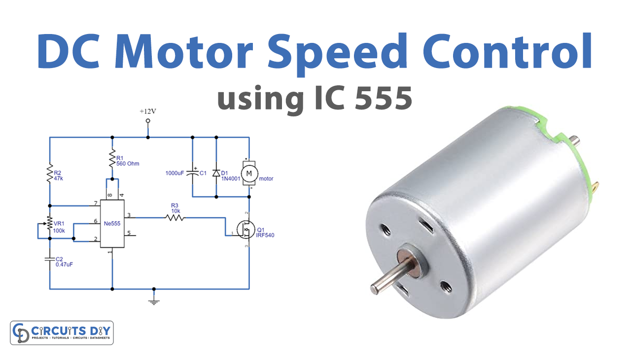
Circuit Diagram

Working Explanation
In this DC motor speed control using IC 555, when we give an input supply of 12V to the circuit, the 555 timer IC generates the pulses at the output pin 3. The pulses depend on the potentiometer wired into the circuit. This output pulse from IC controls the MOSFET connected in the circuit as the output is given the base of the MOSFET which is then wired with the motor to control the speed. Hence, the speed can be controlled or varied by a potentiometer in the circuit.
Application and Uses
- It can be used in conveyor belts to control their speed.
- With some modification, the circuit can be used in industrial purpose applications like rolling mills, and steel mills to control the speed of motors used in various machines.
- Also, in rotating machines, etc.