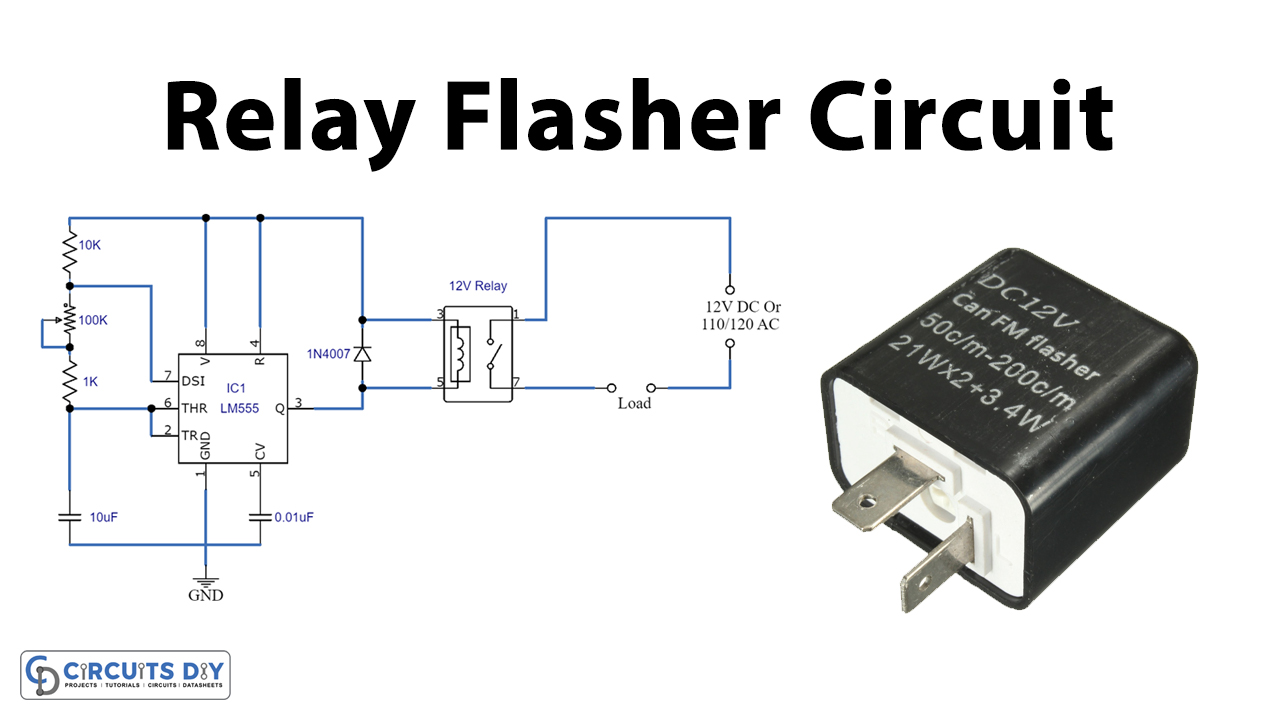
A Relay Flasher circuit is used for operating the flashlights in various ways for many purposes such as a flashlight for a car. The relay needs a certain current draw before it starts flashing tasks, for example, it can be used as a car or motorcycle brake light flasher, headlight flasher, lamp flasher circuit, LED flasher circuit, and able to continuously flash or ON and OFF any AC or DC source.
One of the main use of relay flashers is the hazard and turn signal lights found on the vast majority of road-going vehicles are controlled by a flasher.

Hardware Components
The following components are required to make Relay Flasher Circuit
| S.no | Components | Value | QTY |
|---|---|---|---|
| 1. | Resistors | 10K, 1K | 1 |
| 2. | Potentiometer | 100K | 1 |
| 3. | Capacitors | 10uF, 0.01uF | 1 |
| 4. | IC | NE555 Timer | 1 |
| 5. | Diode | 1N4007 | 1 |
| 6. | Relay | 12V | 1 |
NE555 IC Pinout

For a detailed description of pinout, dimension features, and specifications download the datasheet of 555 Timer
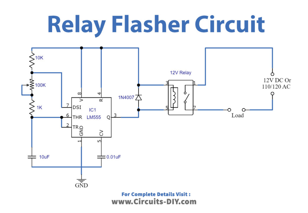
Relay Flasher Circuit
Working Explanation
The 555 timer IC is connected as an astable multivibrator in this circuit and a 12-volt relay is obtained through pin 3 of the IC. The IC produces pulses continuously at pin 3 which will activate and deactivate or flash the relay accordingly. This circuit consists of NE555 IC which is a low-cost IC.
Applications
The relay flasher circuit is commonly used for car headlight or brake light flasher or flashing an AC lamp etc.