In this tutorial, we are going to make a “Servo Motor Driver Circuit”. Servo motors are the small electronic component that helps to rotate or push any part of a machine or device with accurate precision. Unlike generic DC motors, we can control the angle of a servo motor and thus have vast use. These motors are made for precise control of angular or linear position, velocity, and acceleration. Also known as rotary actuators or linear actuators. Servos motors may consist of sensors for position feedback and signal input for position control. These motors are available in different sizes and voltage ratings. A servo motor controller circuit is used to control the position of a servo motor, here we construct a servo motor driver circuit for a sub-micro size servo motor.
Hardware Required
| S.no | Component | Value | Qty |
|---|---|---|---|
| 1. | IC | NE555 Timer | 1 |
| 2. | Resistor | 36KΩ,10KΩ,68KΩ,220Ω | 1,2,1,1 |
| 3. | Switch | – | 2 |
| 4. | Capacitor | 100nf,10nf | 1,1 |
| 5. | Transistor | BC547 | 1 |
| 6. | Connecting Wires | – | – |
| 7. | Power Supply | 9V | 1 |
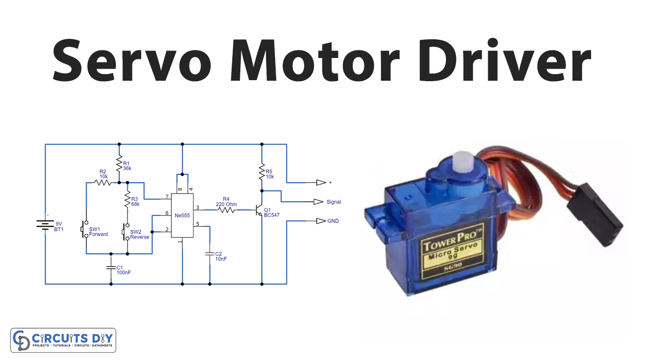
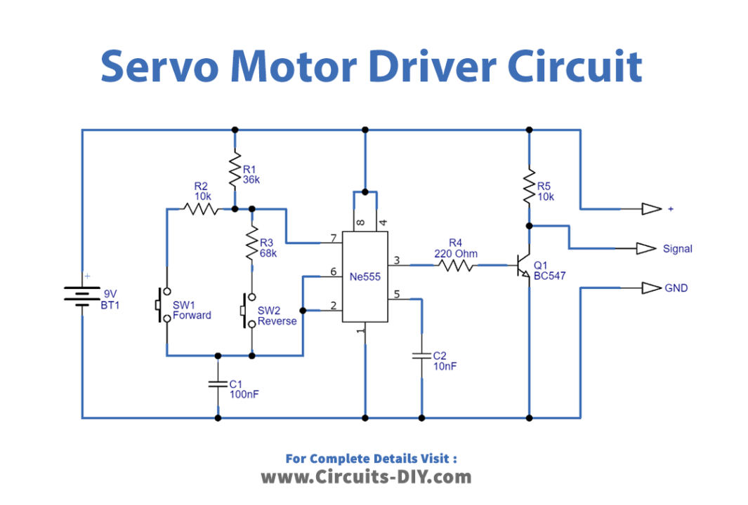
Circuit Diagram
Working Explanation
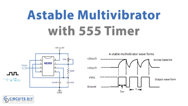
This circuit is designed to give PWM (Pulse Width Modulation) signal output by using different duty cycle PWM pulses. We can control the servo motor rotation and position, by using either the internal PWM module of the microcontroller or the timers. Here we have used timer IC 555 to generate PWM. As soon as you trigger the PWM module (IC 555), the selected PWM channel pin goes high (logic 1.) And after the required width is reached, it will go low (logic 0). Therefore after triggering the PWM, you must start a timer with a delay of specific ms and wait until the timer overflows.
Every servo motor has three terminals one for positive supply, another for ground supply, and one for position control signal input.

To drive the motor, we first need the PWM pulses and that’s why we are using 555 timer IC. While the transistor is in the circuit for the amplification of signals. To understand the servo rotation based on the PWM signal, consider the signal with a 20ms period and width of the HIGH pulse duration of 1ms (min) and 2ms (max). Depending on the HIGH pulse signal time duration servo motor rotation gets changed. As we can see in the circuit, timer IC 555 is employed as an astable multivibrator. It produces a pulse at the output with two different pulse duration, we know that the output pulse time in 555 depends on the timing resistor and timing Capacitor. For the output, we would connect the Vcc wire at Vcc, GND with the ground, and the PWM wire at the collector side of the transistor. Further, we connect switches at the trigger and threshold pins. So, when we apply the voltage and press any switch. The IC gets triggered and the threshold pin compares the applied voltage with a reference voltage of 2/3 Vcc. When we press switch SW1 the IC generates a long-duration high pulse. This high pulse time would be equal to 0.693*(R1 + R2) *C1, and the low pulse time would be 0.693*R2*C1. In this case, the servo rotates in the right direction. When we press switch SW2, this IC generates a short-duration high pulse. This high pulse time would be equal to 0.693*(R1 + R3) *C1, and a low pulse time would be 0.693*R3*C1. In this case, the servo rotates in the left direction. Depending on the output pulse duty cycle, the servo motor’s rotation direction and speed get change.

Applications
The Servo motor controllers are used in:
- Printers
- Solar tracking devices
- Robots
- Antenna positioning frameworks
- Cameras and numerous other modern applications.