In this DIY, we are developing a project of a “Digital Variable Resistor”. A digital variable resistor has a similar function as a typical “potentiometer” however rather than mechanical activity, it utilizes advanced switches and signals. The circuit diagram shows a vital project of a digital variable resistor circuit, the circuit is exceptionally adaptable and can be replaced with any simple variable resistor.
The circuit is having 10 resistances organized that can be chosen by pushing the switch S1, each time the switch S1 is squeezed the circuit will choose the following resistor values from R6, R8, R10, R12, R14, R16, R18, R20, R22, R24.
Hardware Components
The following components are required to make Digital Variable Resistor Circuit
| S.no | Component | Value | Qty |
|---|---|---|---|
| 1. | IC | NE555 Timer | 1, 1 |
| 2. | IC | CD4017 | |
| 3. | Transistor | 2N3904, BC337 | 1, 10 |
| 5. | Electrolytic Capacitor | 10µF | 1 |
| 6. | Ceramic Capacitor | 0.1µF | 1 |
| 7. | Resistor | 1K, 10K, 15K, 2.2K, 3.3K, 4.3K, 5.1K, 6.2K, 7.5K, 8.2K, 9.1K, 180R | 12, 2, 1, 1, 1, 1, 1, 1, 1, 1, 1, 1 |
| 8. | DC Supply | 5V-15V | 1 |
NE555 IC Pinout

For a detailed description of pinout, dimension features, and specifications download the datasheet of 555 Timer
CD4017 Pinout
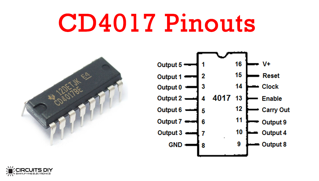
For a detailed description of pinout, dimension features, and specifications download the datasheet of CD4017
Digital Variable Resistor Circuit
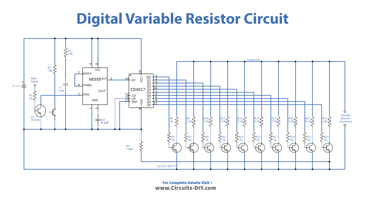
Working Explanation
In this section, we will discuss the circuit operation of the project “Digital Variable Resistor”. The circuit can likewise be controlled with digital input from some other source. The estimations of resistors R6, R8, R10, R12, R14, R16, R18, R20, R22, and R24 can be changed to any necessary qualities or variable resistors can likewise be utilized in the spot of these resistors to get carefully required qualities. The two outputs focus-stamped “Variable Resistor Connections” ought to be associated in the spot of an analog variable resistor.
The circuit is using two ICS, eleven transistors, and just a few other inactive components. The fundamental parts of the circuit are NE555 and CD4017 incorporated circuits. The working voltage can be any from 5V to 15V DC.
Applications and Uses
Digital Variable Resistor is used for:
- Brightness and contrast control of monitors
- Digital-analog converters
- Gain control of Wheatstone bridges