In this tutorial, we are making a project on an automatic knock sensing code lock circuit. This circuit will require codes to activate the appliance connected with the relay at the output of this circuit.
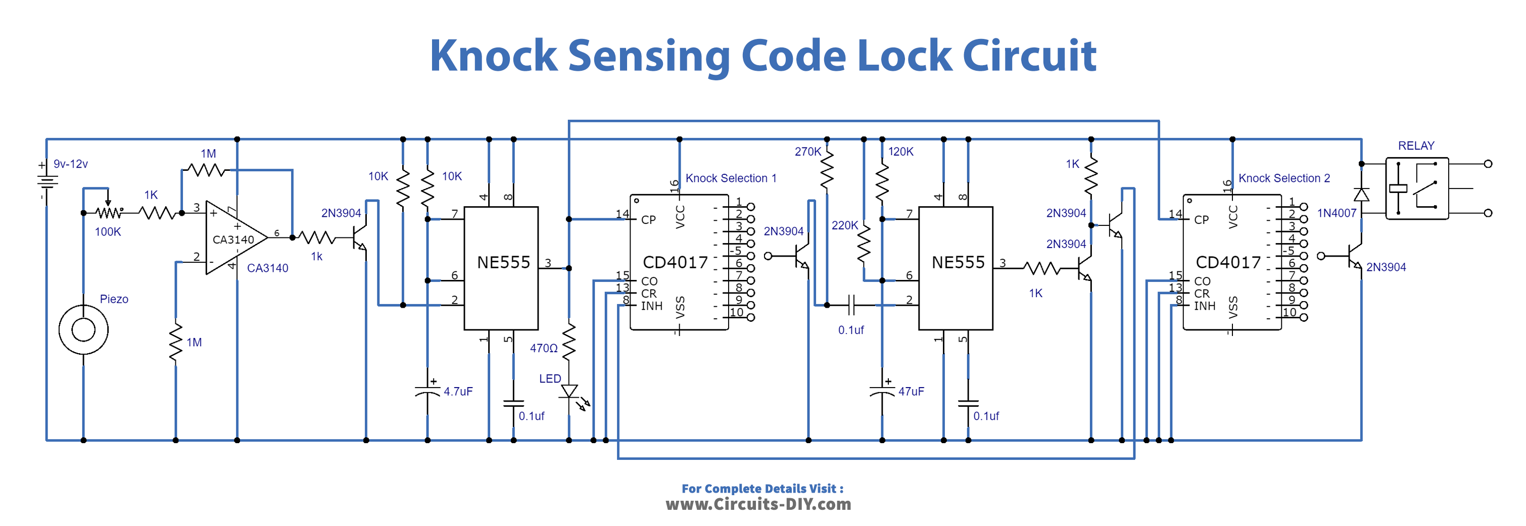
To switch on the relay you have to put two different codes. The codes are selected by two selection points marked in the diagram as knock selection and knock selection 2. For example, if you select number 5 (IC3 pin 10) from the knock selection 1 and no. 7 (IC pin 5) from knock selection 2 then you have to first knock 5 times to switch on the next circuit that is made around IC 4 and 5. Now the next circuit will switch on for 5 seconds and in these 5 seconds, you have to knock 7 times to provide the correct code to switch on the relay. If the knocks aren’t complete then the circuit will take it as the wrong code and won’t move to the second knock circuit and the relay won’t activate
Hardware Components
The following components are required to make Knock Sensing Code Lock Circuit
| S.no | Components | Value | Qty |
|---|---|---|---|
| 1. | Input Supply DC | 9-12V | 1 |
| 2. | IC | CA3140 | 1 |
| 3. | IC | NE555 Timer | 2 |
| 4. | Decade Counter IC | CD4017 | 2 |
| 5. | PZT Sensor | – | 1 |
| 6. | LED | – | 1 |
| 7. | Relay | – | 1 |
| 8. | Transistor | 2N3904 | 5 |
| 9. | Diode | 1N4007 | 1 |
| 10. | Resistors | 1KΩ, 1MΩ, 10KΩ, 470Ω, 270KΩ, 220KΩ, 120KΩ | 1, 1, 2, 1, 1, 1, 1 |
| 11. | Electrolytic Capacitor | 4.7µF, 47µF, 0.1µF | 1, 1, 3 |
| 12. | Variable Resistor | 100K | 1 |
CA3140 IC Pinout

For a detailed description of pinout, dimension features, and specifications download the datasheet of CA3140
NE555 IC Pinout
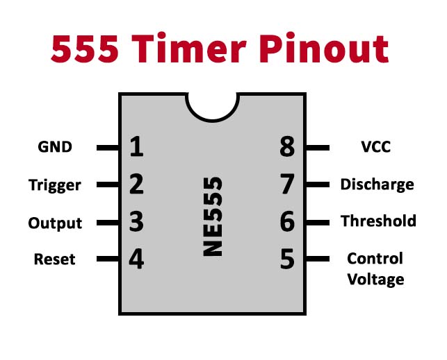
For a detailed description of pinout, dimension features, and specifications download the datasheet of NE555 IC
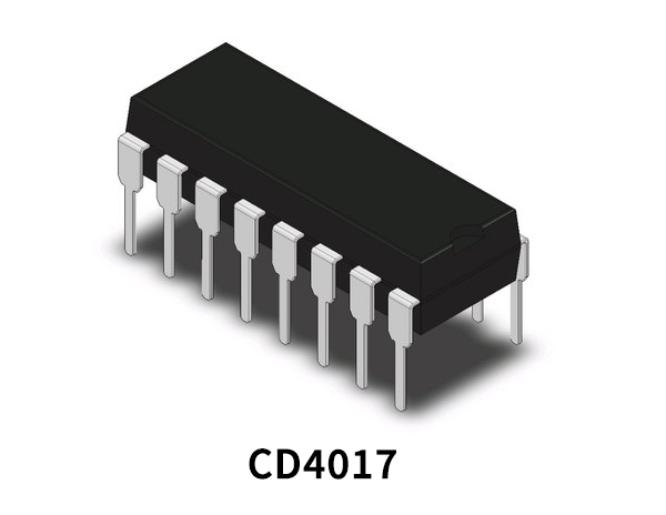
CD4017 Pinout

For a detailed description of pinout, dimension features, and specifications download the datasheet of CD4017
Knock Sensing Code Lock Circuit
Working Explanation
The circuit is working on the combination of 5 ICs as seen in the circuit diagram. One is working as a comparator, two of them are providing time delays and the other two are decade counters. A piezoelectric sensor is used to sense the knocks. The sensitivity of the knocks is adjusted with the 100K variable resistor. The LED at the output of the IC2 will blink whenever a knock is sensed. This circuit is operated at 9 to 12 volts DC, it can also be operated on lower voltages like 5 or 6 volts. Make sure to use the relay of the same voltage. For better results attach the piezo at the backside of the place of knocks, if you are using this for the storage box then put the piezo at the inside of the door where you desire to knock
Application and Uses
- Doors
- Safety boxes
- Security purposes