In this tutorial, we are making an Early Car Battery failure circuit. It will give an early indication of the failure of your car battery by activating a buzzer for a few seconds. In this way, you will know beforehand that your battery is now near to failure.
The battery that your car owns is a lead-acid battery which helps to start the engine. This battery lasts for 4-6 years. When it is new it drops only 2 volts during cranking but as the time passes and the battery gets old it starts dropping 5-6 volts due to which the car engine doesn’t start. This circuit will solve this problem by measuring the voltage drop of the battery. It produces an alarm through a buzzer when the battery’s voltage drops to 8V while cranking.

Hardware Components
The following components are required to make Battery Failure Detector Circuit
| S.no | Component | Value | Quantity |
|---|---|---|---|
| 1. | Cigarette Lighter Plug | – | 1 |
| 2. | IC | NE555 Timer | 1 |
| 3. | Zener Diode | 3.3V | 1 |
| 4. | Resistor | 27K, 8.2K | 1, 1 |
| 5. | Variable Resistor | 10K | 1 |
| 6. | Capacitor | 10nF, 470uF/16V | 1, 1 |
| 7. | Piezo buzzer | – | 1 |
NE555 IC Pinout

For a detailed description of pinout, dimension features, and specifications download the datasheet of 555 Timer
Battery Failure Detector Circuit
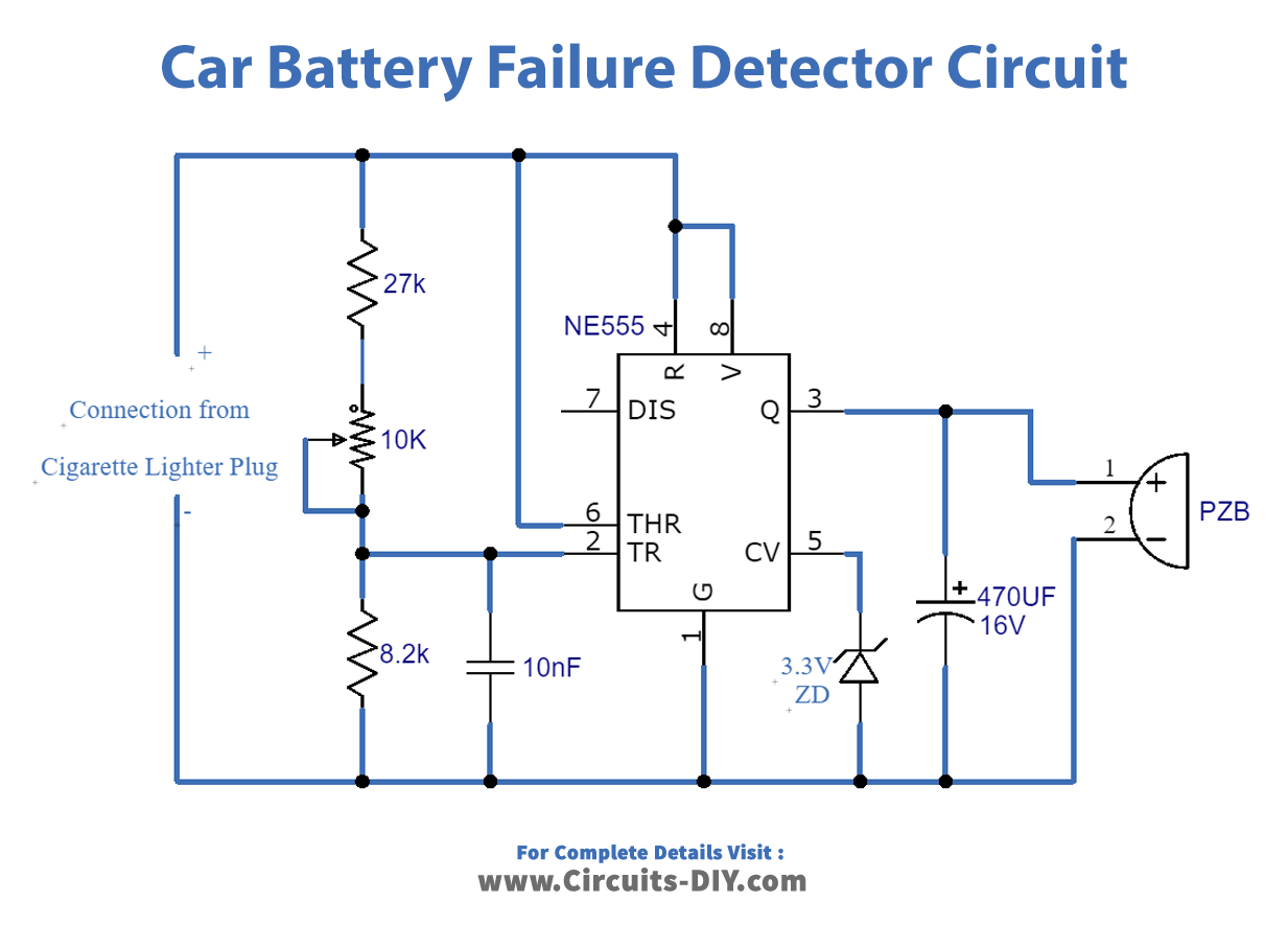
Working Explanation
The main component of this circuit is a 555 timer IC which is working in a comparator mode. The input supply is given from a cigarette lighter plug in your car. A variable resistor is used to adjust the frequency of the 555 timer IC. For the alarm, we are using a piezo buzzer.
Circuit Adjustments
After building this circuit there are some adjustments needed to be done while tuning this circuit for the first time. For that, you will need a variable power supply.
- After completing the circuit do not connect it with the cigarette lighter connection.
- Set the voltage to 8V in the variable power supply and connect the circuit with it.
- Adjust the 10K variable resistor until the buzzer produces a sound.
- Now remove the variable power supply and connect it with the cigarette lighter connection your circuit is ready to start.
- For accuracy make sure the circuit is fitted in a suitable enclosure.