The free-running or self-triggering mode of the 555 timer IC is known as the Astable Multivibrator mode of 555 timer IC. As we have discussed in the previous article about the monostable state, in which there are two states, one is stable, and the other is unstable.
But in the Astable Multivibrator mode of 555 timer IC, we have two states, and both states are unstable or quasi-stable states. The one unstable state is High, and the other is Low. in this mode, we do not require any external triggering for switching the state.
In this tutorial, we are demonstrating a project of a 555 Timer Astable Multivibrator Circuit, which is easy to demonstrate and requires a few components.

Hardware Component
The following components are required to make Astable Multivibrator Circuit
| S.no | Component | Value | Qty |
|---|---|---|---|
| 1. | LED | – | 1 |
| 2. | Switch | – | 2 |
| 3. | Battery | 9 V | 1 |
| 4. | IC | NE555 timer | 1 |
| 5. | Capacitor | 0.01uF, 10uF | 1, 1 |
| 6. | Resistor | 1K, 100K, 220 Ohms | 1, 1, 1 |
NE555 IC Pinout

For a detailed description of pinout, dimension features, and specifications download the datasheet of NE555 IC
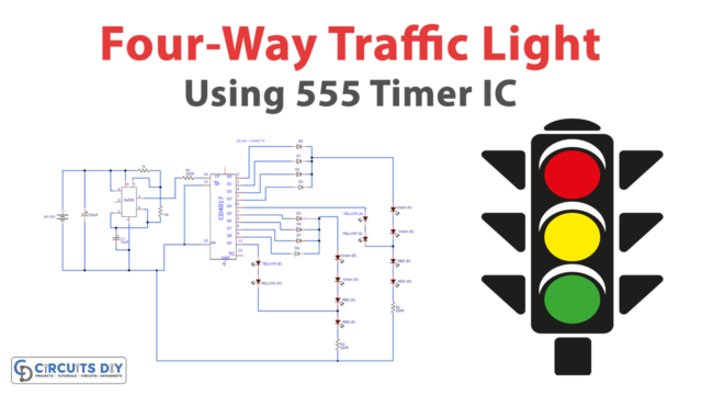
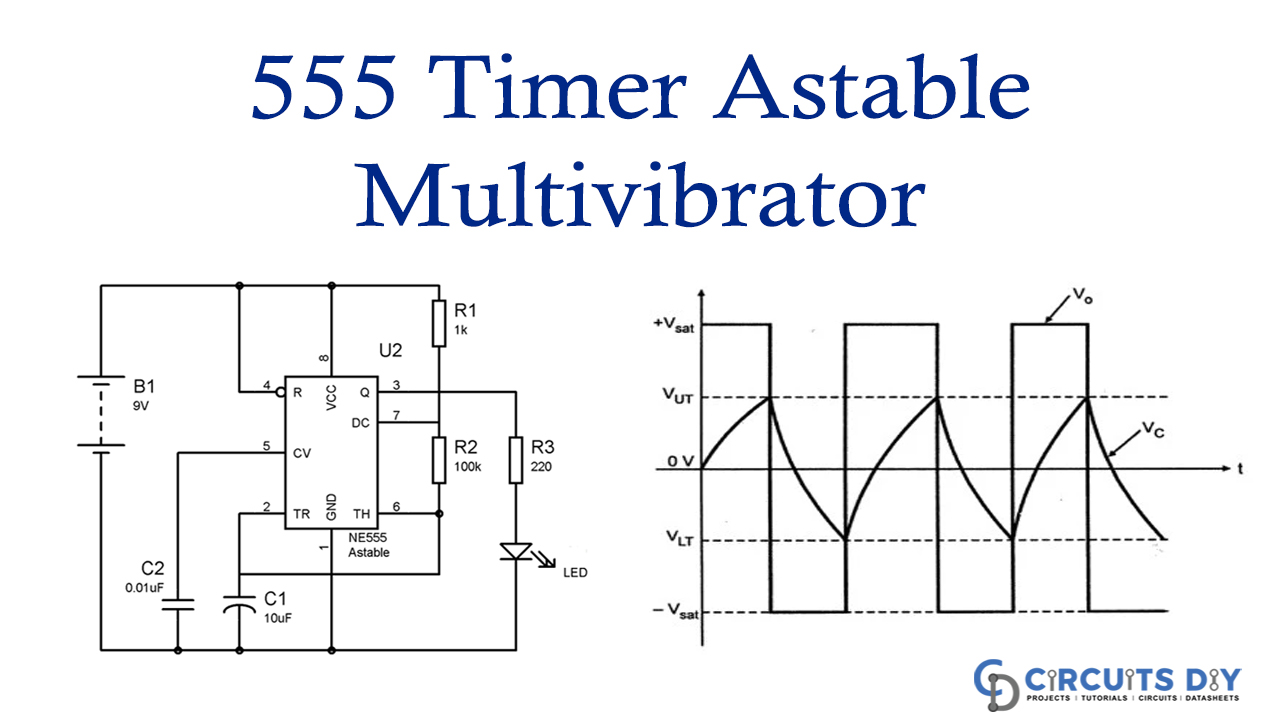
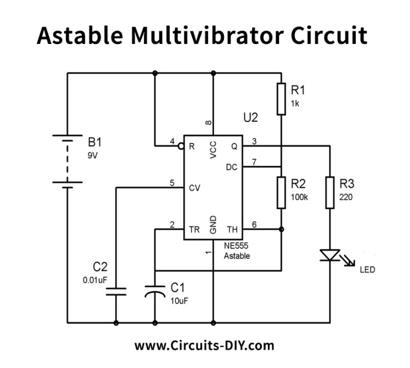
Astable Multivibrator Circuit
Working Explanation
In this section, we are discussing the project of a 555 Timer Astable Multivibrator Circuit in which we will demonstrate the astable mode of 555 timer IC. We have associated the LED with the output of the 555 Timer IC for demonstrating the astable mode of the 555 timer IC.
LED will turn ON and OFF consequently with a specific term in this 555 astable multivibrator circuit. The formulae are given to calculate the ON time, off time, frequency, etc.
Time High (T1) = 0.693 x (R1+R2) x C1
and Time Low (T2) = 0.693 x R2 x C1
Time Period (T) = T1 + T2 = 0.693 x (R1+2xR2) x C1
Frequency (F) = 1/T = 1/ 0.693 x (R1+2xR2) x C1 = 1.44 / (R1+2xR2) x C1
Duty cycle %= (T1/ T) x 100= (R1+R2)/ (R1+2xR2) x100
Applications and Uses
Frequency modulated signals can be generated with the help of an Astable multivibrator.