Mosquito repellers are used for the whole night, which decreases their power. Since almost all the reports work on 5 watts. Hence, it’s relatively power-consuming. So, for this reason, power-saving devices earned a lot of attention. Power savers reserve the electricity inside. And, release it when the user needs that. It uses capacitors for this purpose. The main objective of the Mosquito repeller power saver is to provide a backup system in the duration of low current. Also, it protects the repeller and increases its life and energy.
Our repeller circuit uses NE555 timer IC as the main component. Certainly, Capacitors are also here in the circuit to store the energy and to discharge that energy when requires. Thus, To adjust the ON/Off intervals, the circuit needs the potentiometer. Most importantly, remember to assemble the circuit on a good-quality board.
Hardware Required
| S.no | Component | Value | Qty |
|---|---|---|---|
| 1. | Vero board/ PCB Board | – | 1 |
| 2. | IC | NE555 Timer | 1 |
| 3. | Diode | 1N4007 | 3 |
| 4. | Transformer | – | 1 |
| 5. | Resistor | 1K, 10K | 1, 1 |
| 6. | Potentiometer | 470K | 1 |
| 7. | Capacitor | 470uF, 0.1uF | 2, 1 |
| 8. | Transistor | SL100 | 1 |
| 9. | SPSDT Switch | 12V | 1 |
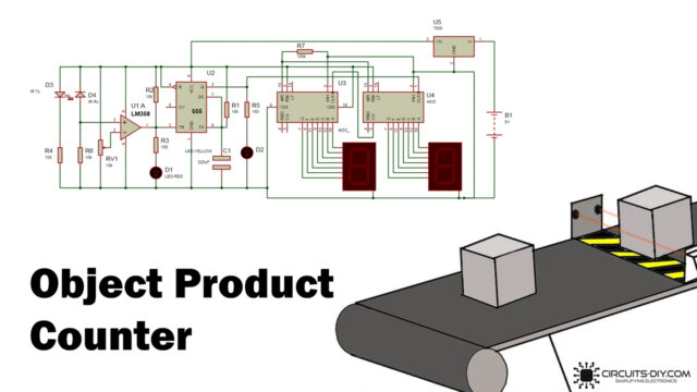
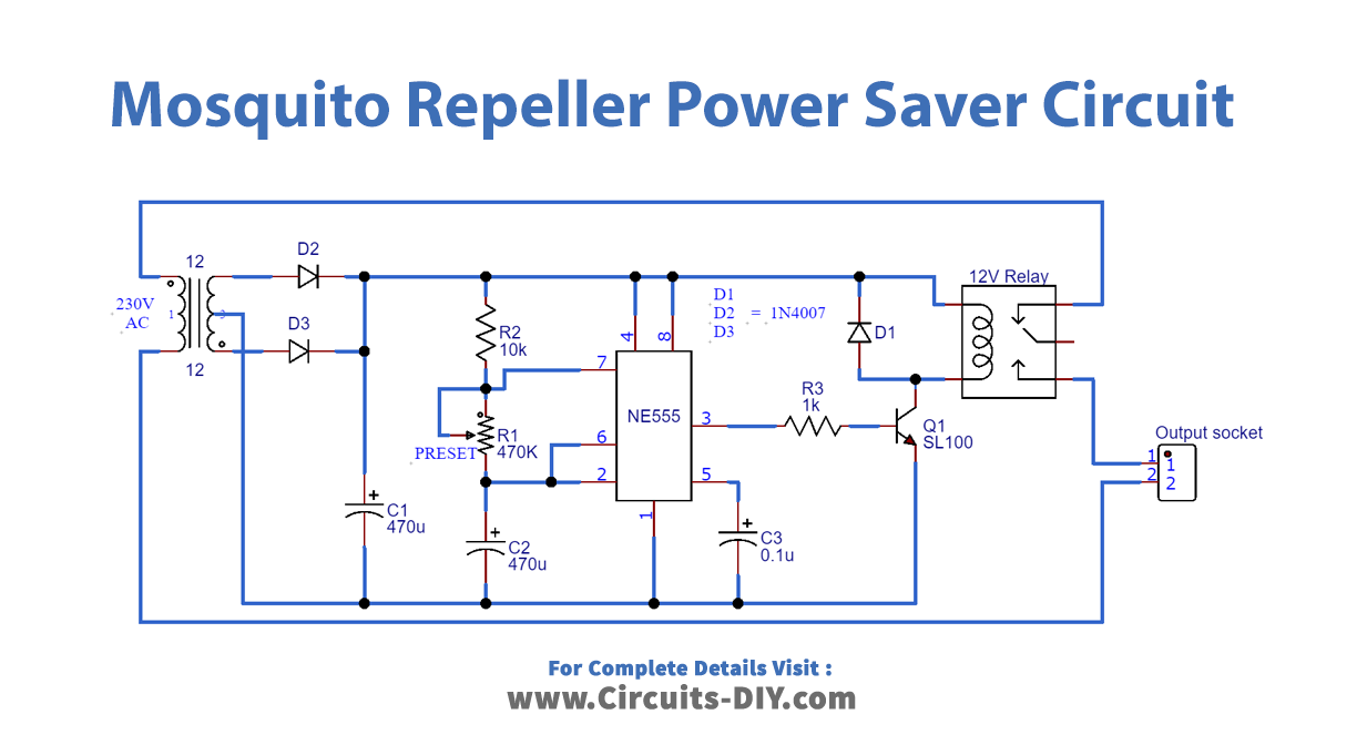
Circuit Diagram of Mosquito Repeller Power Saver
Working Explanation
When the Mosquito Repeller Power Saver is turned ON, the output pin 3 of the multivibrator IC goes high. Hence, this output makes the transistor conduct. And, the transistor drives the relay that is wired into the circuit. After the set time, when the repeller gets removed from the power saver, IC goes low. That’s how the circuit works.
Application
Certainly, the circuit is mainly used to save the power of mosquito repellers. But, with some improvement, it can be used by different appliances to save power.