
In this tutorial, we are going to make an “Inverter Circuit using IC 555 “. An inverter is nothing but a DC-to-AC converter ( a power electronic device or circuitry that changes direct current (DC) to alternating current (AC). The resulting AC frequency obtained depends on the particular device employed). Inverters are very useful electronic products for compensating for emergency power failure, as it performs DC to AC conversion. Here we don’t need a pure sine wave inverter or bulk inverter with high power if the load connected to the inverter circuit is very small. Therefore we can create a simple small inverter circuit to handle low-power devices. Here we design an inverter by using 555 IC and easily available components.
Hardware Required
| S.no | Component | Value | Qty |
|---|---|---|---|
| 1. | IC | NE555 Timer | 1 |
| 2. | Transistor PNP | TIP41A | 1 |
| 3. | TransistorNPN | TIP41A | 1 |
| 4. | Transformer AC with frequency | 50Hz, 60Hz /110V, 230V | 1 |
| 5. | Resistor | 10KΩ,100KΩ,100Ω | 1,1,1 |
| 6. | Variable Resistor | 50KΩ | 1 |
| 7. | Capacitor | 0.1uf,0.01uf,2200uf | 1,1,1 |
| 8. | Connecting Wires | – | – |
| 9. | Battery | 15V | 1 |
Circuit Diagram
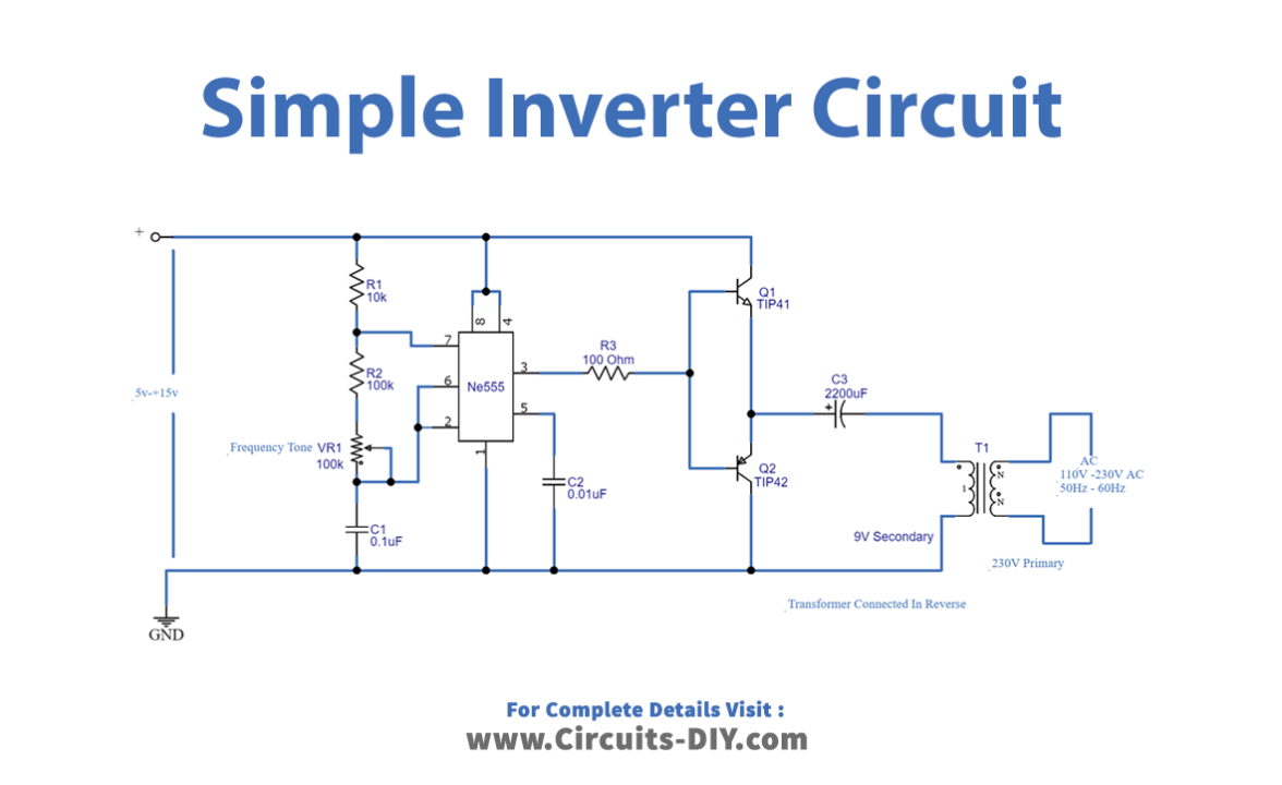
Working Explanation
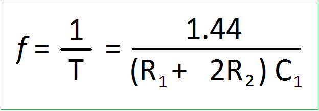
Here IC 555 is a main part of the circuit, it is employed as a switching pulse oscillator. For continuous switching pulse, 555 IC has to configure as Astable Multivibrator. The transformer T1 is 230V primary to 9V secondary but connected in reverse, so it can react as a step-up transformer. Here two switching transistors TIP41A (NPN) and TIP42A (PNP) drive the transformer T1 according to the pulse input at the base. We can apply +5V to +15V DC bias to this circuit and get 110V to 230V AC with 50Hz to 60Hz frequency. Use a heat sink for transistors to avoid overheating, and use a 1 A to 1.5A transformer. But the output of this circuit may not be pure sine wave as the PWM inverter output, it gives only pulsated AC. The output frequency can be varied by varying VR1 resistors. The following formula is to calculate the output AC supply and frequency.
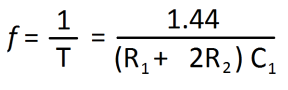
Here R2 = R2+VR1 from the given circuit.
How does Switching Inverter work?
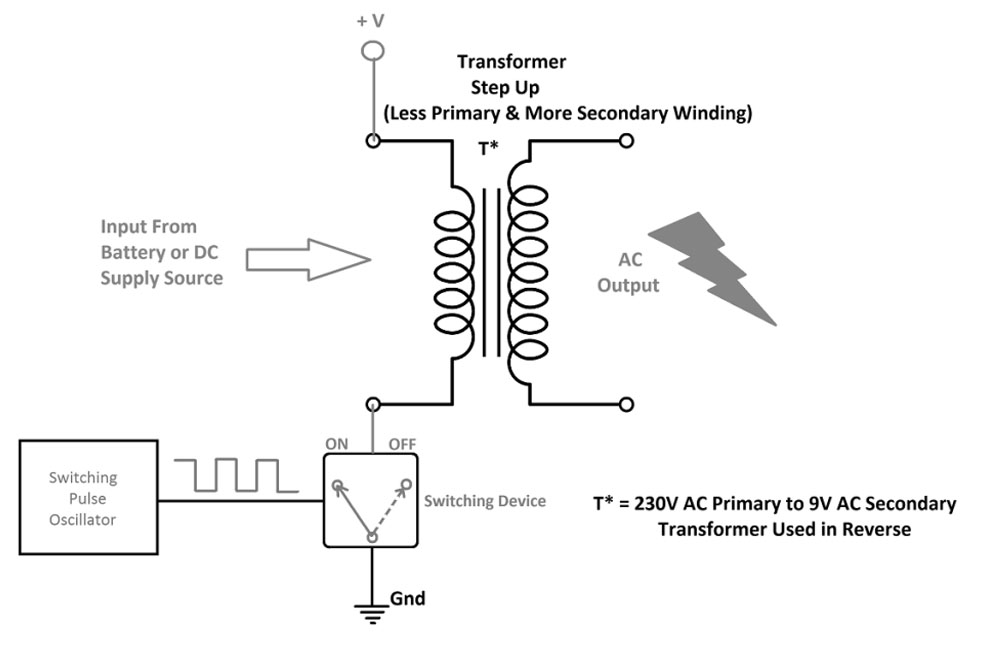
The switching function in inverters is needed to alternate the direction of the DC current in order to produce AC power. Usually, electronic semiconductor devices are used to perform switchings, such as transistors and thyristors. But thyristors are used in basic models of inverters. Here let’s consider the transformer with a less primary and more secondary winding, for example, 230V AC primary to 9V AC secondary used in reverse. Now, the less winding side becomes primary and the more winding side becomes secondary. DC bias is applied in one terminal and -ve or ground connected in another pin through a switching device. If the switch is ON primary winding gets DC bias, and when the switch is OFF primary winding is disconnected from the DC bias. By the way, a 50Hz switching pulse drives the switching device so the winding gets discrete DC bias. Here magnetic flux produced from the primary winding induces more coil secondary, so the high voltage EMF is induced at the secondary.
Application
Inverter circuits are very helpful during power cuts and as portable power sources.


