Introduction
To understand the creation of energy through sound vibration. The microphone identifies the intensity of the sound. Inside the microphone, there is a diaphragm. When the clap sound hits the diaphragm, it vibrates and changes the capacitance. With the changing of capacitance, voltage changes and that’s how it takes and passes the signal forward which we will discuss in the working explanation. A load of this circuit gets turned on or off by the human hand clap. This simple circuit is very suitable for beginners. So, In this tutorial, we are going to “Clap Switch Circuit with Relay”
Hardware Required
| Sr.no | Component | Value | Qty |
|---|---|---|---|
| 1. | IC | NE555 Timer | 1 |
| 2. | IC Dual D flip flop | 7474 | 1 |
| 3. | Relay (SPDT) | 5V | 1 |
| 4. | Condenser Mic | – | 2 |
| 5. | Transistor | BC547 | |
| 6. | LED | – | 1 |
| 7. | Diode | 1N4007 | 1 |
| 8. | Capacitor | 10μF, 0.01μF | 1, 1 |
| 9. | Resistor | 43KΩ, 1KΩ, 100KΩ, 330Ω | 1, 1, 1, 1 |
| 10. | Battery | 9V | 1 |
| 11. | 2-Pin Connector | – | 1 |
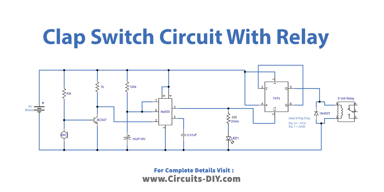
Circuit Diagram
Working Explanation
This Clap Switch Circuit involves three stages. At first, there is a sound detector stage that has been formed by using a Condenser mic and BC547 transistor. In the second stage, there is timer IC NE555, and we are using this IC as a monostable multivibrator. Hence it will generate a timing pulse depending on the timing resistor and capacitor, R3 and C1 respectively. We immediately gave the output of a timer IC to the third stage which has a D flip-flop. Now, the input pulse drives the D flip-flop into either set or reset. Then, we connected the Relay at the Q pin, which is the output of the D flip-flop. The relay becomes energized and turns ON the load during the set condition while turning OFF the load during the Reset condition.
Application and Uses
- Hearing aid devices.
- Speed recognition equipment.
- Sound-sensitive electronic gadgets.
- Home and industrial automation systems.
- Tape recorders, etc