A darkness detector is basically a Light Dependent Resistor (LDR) interfaced generator of the square wave. LDRs are created from materials of semiconductors to permit them to attain their sensitive properties of light. These LDRs work on the principle of “Photo Conductivity” which means that the conductance of the element is increased after the falling of light on the surface of the LDR.
The IC of the 555 timers is used as a dark detector in its mode of single shot or monostable mode.
Hardware Required
| S.no | Component | Value | Qty |
|---|---|---|---|
| 1. | IC | NE555 Timer | 1 |
| 2. | Light Dependent Resistor (LDR) | of any size | 1 |
| 3. | Speaker | 8 ohm | 1 |
| 4. | Variable resistor | 10K or 1M | 1 |
| 5. | Resistor | 1.2K, 47K, 1K | 1,1,1 |
| 6. | Capacitor | 47uF, 0.05uF | 1,1 |
| 7. | DC Supply | 9-volt to 12 volt | 1 |
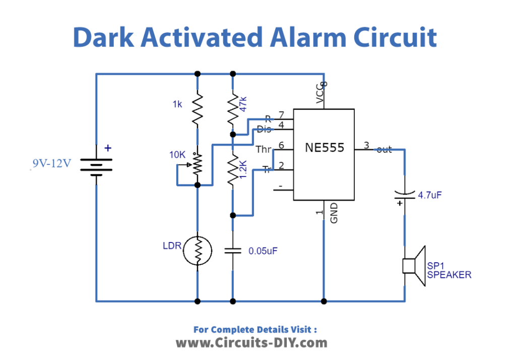
Circuit Diagram
Working Explanation
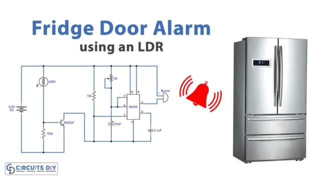
The circuit of the light-activated alarm using 555 timer IC generates sound when the light falls on the outward side of light Dependent Resistor (LDR). The significant part of the circuit is the 555 timer IC that is connected to the circuit as an astable multi-vibrator. An LDR is used as a sensor of darkness. A variable resistor of 10k is used to regulate the circuit to stimulate the alarm on the necessary level of darkness. A speaker of 8 ohms is connected with a capacitor of 4.7 microfarads and produces output in the form of sound. By altering the value of the capacitor of 0.05 microfarad, the frequency of the sound is changed. The circuit operates at the DC voltage of 9 volts to 12 volts. The best result of the circuit is obtained when it is placed in a suitable enclosure.
Application and Uses
• The circuit of dark-activated alarm by using 555 timers IC signifies the nonexistence of light or the existence of dark in a definite region.
• The circuit of the dark-activated alarm using 555 timers IC can be used in the system of home security or home automation.