As op-amp, IC 741 and timer IC 555 are the critical components in electronics that utilize in a variety of circuits. If the constructed circuit is not giving proper output, and sometimes it stops working and we get no clue what the reason behind it is. There can be so many reasons. For example, the defective IC that you have used in your circuit. So we need to check every component in the circuit and can change the faulty ones. But if the problem is in IC, then we cannot easily identify that problem. Here we design a simple circuit to check the faulty 741 IC and 555 IC.
Hardware Required
| S.no | Component | Value | Qty |
|---|---|---|---|
| 1. | IC | IC741, NE555 Timer | 2 |
| 2. | 8-pin IC Base | – | 1 |
| 3. | LED Green | – | 2 |
| 4. | LED Red | – | 1 |
| 5. | Resistor | 68KΩ,33kΩ,1.2kΩ, 4.7kΩ | 1,1,2,2 |
| 6. | Capacitor | 10uF/16V,0.01uF | 1,1 |
| 7. | Switch | – | 1 |
| 8. | Connecting Wires | – | – |
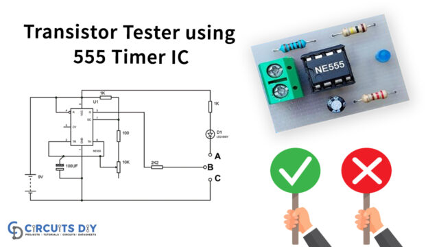
Circuit Diagram
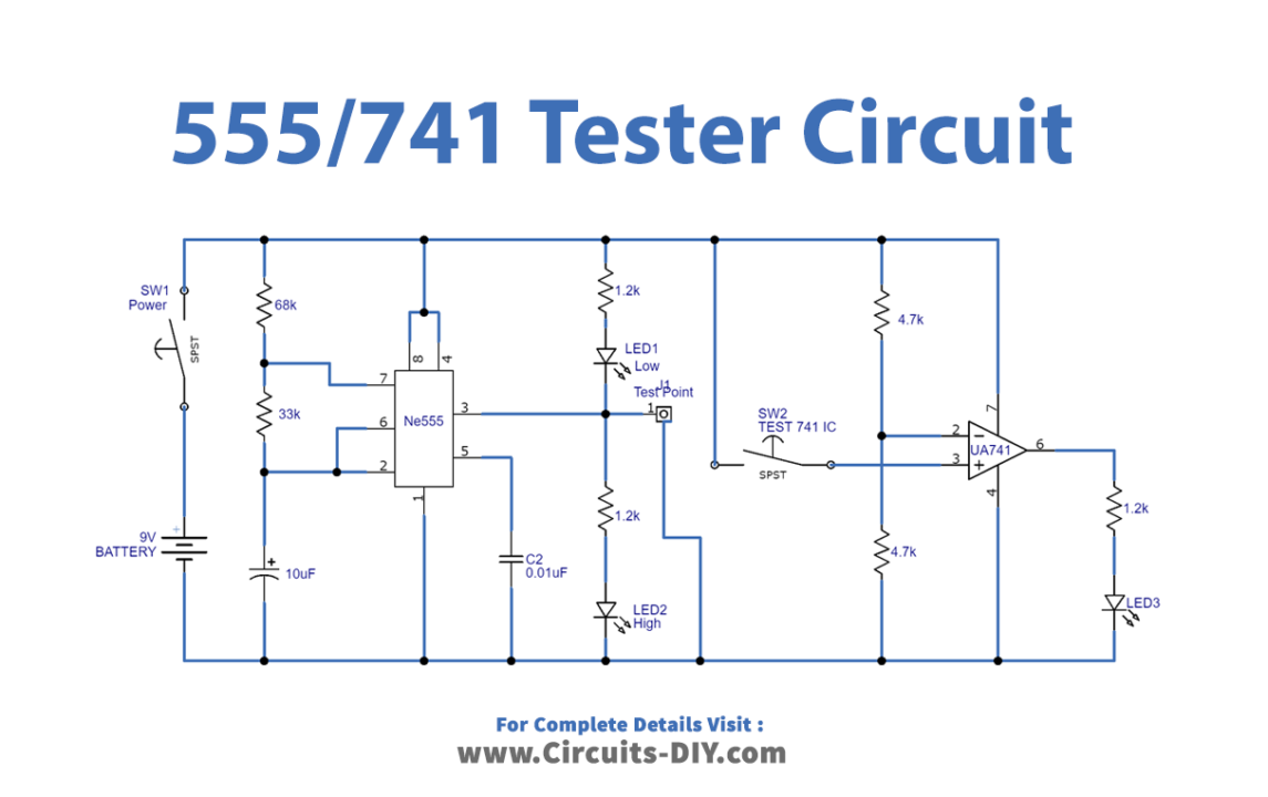
Working Explanation
As in this circuit, we need to test the two most common ICs that is Timer IC555 and operational amplifier IC741. Here use 8 pin IC base for both the timer and op-amp IC. Now if we want to first check IC555 place the testing IC in the base and watch the output LEDs. If the two output LEDs connected with pin number 3 glow alternately means the tested IC is good otherwise this can be a faulty IC. In the same way, if you test IC741, for this the output LED connected with IC741 should glow otherwise it can be a faulted IC.
Applications
Can be used to test 741 IC and 555 IC in any circuit.