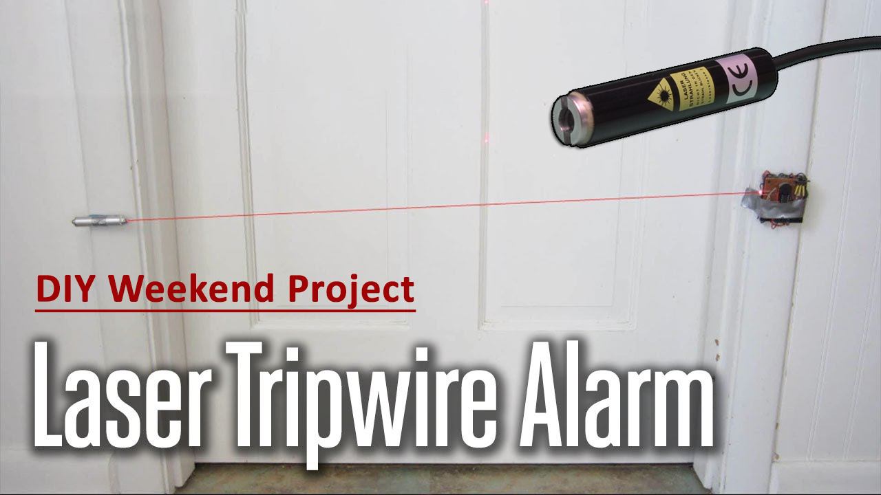
What is a Laser Tripwire Security Alarm?
A laser tripwire security alarm is a simple security system that can detect the movement of any intruding person or object passing through the beam of a laser & triggers an alarm accordingly. The red line laser actually triggers a latching switch, that can be connected to any external load/security device such as a loudspeaker alarm, floodlight, or CCTV cameras. Laser tripwire alarms have become a staple for home security systems & mandate their presence in every security detail for any place. So, in today’s tutorial, we will go over a step-by-step procedure on how to design a simple Laser Tripwire Security Alarm using an LDR & a NE555 timer IC.
The heart of this laser security system is a light-dependent resistor or an LDR. LDRs are electronic components that are sensitive to light intensity. Its behavior is similar to a photocell that works on the principle of photoconductivity. The resistance value of an LDR decreases when the intensity of light increases. The threshold voltage of the NE555 timer IC is decided by the output voltage of the voltage divider configuration (LDR & R2), here the NE555 is running in astable (free running mode).
JLCPCB is the foremost PCB prototype & manufacturing company in china, providing us with the best service we have ever experienced regarding (Quality, Price Service & Time).
Hardware Components
The following components are required to make Laser Tripwire Alarm Circuit
| S.no | Component | Value | Qty |
|---|---|---|---|
| 1. | Laser diode/pointer | 5V, 650nm, 5mW | 1 |
| 2. | IC | NE556 Timer | 1 |
| 3. | Laser Security Alarm PCB | AllPCB | 1 |
| 4. | LDR | 5mm | 1 |
| 5. | Electrolytic Capacitor | 100uF, 470uF | 1 |
| 6. | Ceramic Capacitor | 0.1uF | 2 |
| 7. | Resistor | 1K, 10K, 22K | 2 |
| 8. | Soldering Iron | 45W – 65W | 1 |
| 9. | Transistor | 2n3904 | 1 |
| 10. | DC Battery | 9V | 1 |
| 11. | Speaker | 8 ohms | 1 |
| 12. | Jumper wires | – | As per need |
NE556 Pinout
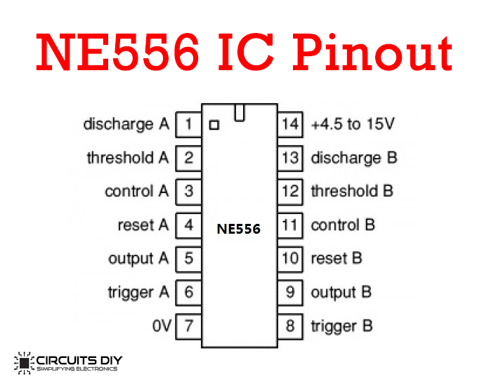
For a detailed description of pinout, dimension features, and specifications download the datasheet of NE556
Laser Tripwire Alarm Circuit

Working Explanation
This laser tripwire circuit triggers an alarm when the line of sight between the laser beam & the LDR is interrupted. The design of this circuit is based on a 555 timer IC. A photoresistor (LDR) is used to detect the laser light from the laser diode. The LDR & the 220Ohm resistor together form a voltage divider circuit.
When the laser beam is interrupted, the light intensity over the LDR decreases, increasing its resistance, this causes the voltage at pin 6 (Threshold) to rise above the reference threshold voltage. This triggers the output at pin 3 (Output) to go low & activate the Buzzer. When the line of sight between the laser pointer & the LDR is re-established its resistance decreases, causing the voltage divider output to fall well below the reference threshold voltage at pin 6 of the IC, disconnecting the output pin 3 from the latch switch which turns off the alarm.
Applications
- Laser security alarms are used in places such as residential, commercial, industrial, and military properties for protection against theft or property damage.
- Also used in high-risk/sensitive areas such as military bases, security vaults & supermax prisons.