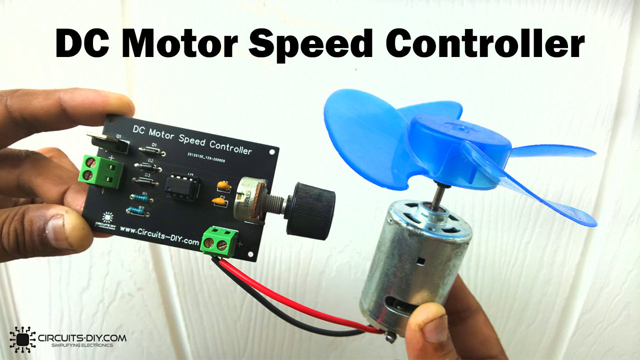
Introduction
DC motors have a great range of applications in electronic devices. If you’re an electrical student, then you must have seen its applications. or you must have used it in various projects. Apparently, DC motors are in every other application, either industrial or at an academic level. So, Learning to control the speed of the DC motor Speed is an essential thing to discuss. Different applications require different speed levels of the DC motors for their project or machine.
For instance, robotic cars may not want the backward speed the same as the forward speed. In the same vein, some industrial devices work at different levels of speed. So, in this article, we will take a look at how you can easily design a PWM DC Motor Controller with a NE555 timer IC using & a small number of other components.
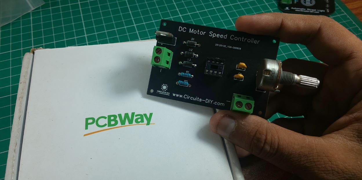
PCBWay commits to meeting the needs of its customers from different industries in terms of quality, delivery, cost-effectiveness, and any other demanding requests. As one of the most experienced PCB manufacturers in China. They pride themselves to be your best business partners as well as good friends in every aspect of your PCB needs.
Hardware Components
The following components are required to make DC Motor Speed Controller Circuit
| S.no | Component | Value | Qty |
|---|---|---|---|
| 1. | DC Motor | 12V/6000 – 10000RPM | 1 |
| 2. | PWM DC Motor Controller PCB | PCBWay | 1 |
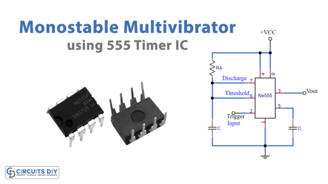
| 3. | IC | NE555 Timer | 1 |
| 4. | Darlington Transistor | TIP122 | 1 |
| 5. | Potentiometer | 100K | 1 |
| 6. | Diode | 1N4007 | 3 |
| 7. | Capacitors | 100nF | 2 |
| 8. | Resistors | 1K | 2 |
| 9. | Soldering Iron | 45W – 65W | 1 |
| 10. | Soldering Wire with Flux | – | 1 |
| 11. | DC Battery | 12V | 1 |
| 12. | Battery Clips | – | 1 |
| 13. | Soldering Stand | – | 1 |
| 14. | Jumper Wires | – | As per need |
TIP122 Pinout
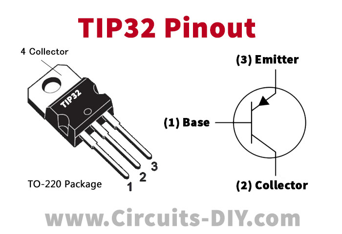
For a detailed description of pinout, dimension features, and specifications download the datasheet of TIP122
NE555 IC Pinout

For a detailed description of pinout, dimension features, and specifications download the datasheet of NE555 IC
DC Motor Speed Controller Circuit
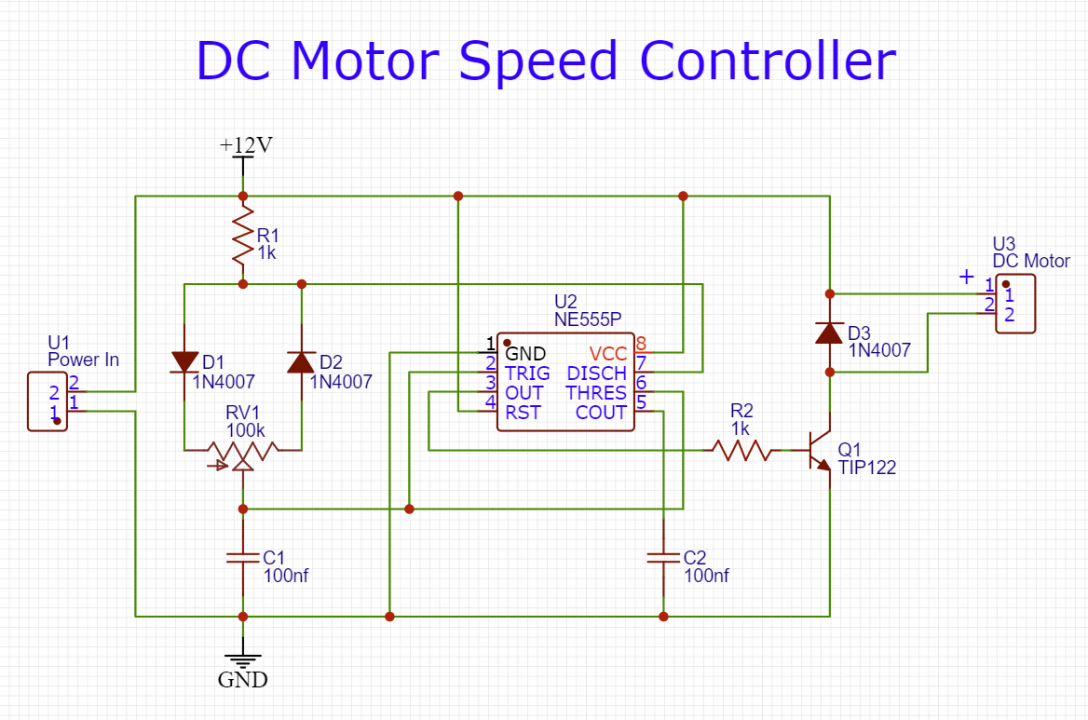
Working Explanation
In this DC Motor Speed Control, IC 555 is working as a square pulse generator depending on the value of the potentiometer. The output pulse width or duty cycle can get changed through that potentiometer. Someone immediately gave the output from IC 555 to the base of the wired transistor. We have connected the motor to the collector of the transistor through the diode. Now, you can adjust the speed by adjusting the potentiometer in the circuit.
Applications
- In industries, we can use it in Conveyor belts.
- In consumer products, DC fans can utilize this circuit.
- Robotic cars can employ these circuits to control their speed.
- Automation circuits.
- It also has some medical applications.