Introduction
Ultrasonic alarms emit high-frequency sound waves that are not audible to the human ear but can be used to detect the presence of objects or movements within a specific range. These alarms are widely used in various applications, such as security systems, industrial automation, and robotics. In this article, we will show you how to build a simple ultrasonic alarm circuit that can detect the presence of objects or movements within a specific range and trigger an alarm.
The circuit is simple to build and can be fun for anyone interested in electronics and sensor technology. So, let’s make it!
Components Required
You will require the following hardware for Ultrasonic Alarm Circuit.
| S no | Components | Value | Qty |
|---|---|---|---|
| 1 | IC | 741 | 1 |
| 2 | Capacitor | 470nF | 3 |
| 3 | Resistor | 6k8, 10k, 1M, 100K, 12K, 4K7 | 1, 1, 1, 1, 1, 1 |
| 4 | Diode | 1N4148 | 1 |
| 5 | Mic | – | 1 |
Steps to Build the Ultrasonic Alarm Circuit
You need to follow the given circuit diagram and connection to make the Ultrasonic Alarm Circuit.
Circuit Diagram

Connections
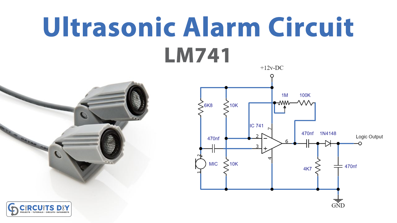
- Connect the condenser microphone to the inverting input of the IC 741 at pin 2
- Connect pin 3 of the IC to a reference voltage with respect to pin 2 of the IC
- Connect a 1M preset between the output and the inverting input of the IC to create a feedback loop
- Connect a 470nF coupling capacitor between the output and the diode, resistor, and capacitor filter layout
- The IC’s high logic at pin 6 can be used as an input to a microcontroller circuit or to operate a relay driver stage.
Working Explanation
The above circuit is an ultrasonic alarm circuit that uses an IC 741 integrated circuit as its core component. The detection device used in this circuit is a standard electret condenser microphone. The microphone input is provided to the inverting input of the IC at pin 2. Pin 3 of the IC is effectively clamped to a reference voltage with respect to pin 2 of the IC. The circuit also includes a 1M preset that connects the output and inverting input of the IC, creating a feedback loop that causes the IC to function as a highly sensitive inverting amplifier. We can adjust the level of sensitivity of the ultrasonic alarm circuit by adjusting the 1M preset.
When the microphone detects high-frequency audio in the ultrasound spectrum, it results in a high logic pulse at pin 6 of the IC. The output architecture can further shape and purify this pulse, including the 470nF coupling capacitor and the relevant diode, resistor, and capacitor filter layout. The high logic can be used as an input to a microcontroller circuit or to operate a relay driver stage.
Final Words
The ultrasonic alarm circuit is a great way to trigger an alarm when something or someone moves within a certain range. It’s a low-cost and easy-to-build project and is a great way to learn about ultrasonic technology and electronics. You can use it for security systems, to detect movements in the dark, or even for industrial automation. Happy learning!