Introduction:
Security is a thing which is needed everywhere around. We can create a simple & secure detection system based on Infrared LED (transmitter), a photodiode (receiver), and a 555 timer IC. IR led continuously emits infrared rays while the photodiode which is acting as a receiver receives these rays and generates a signal while 555 timer IC which is working in Astable multivibrator mode turn on and off the output buzzer depending on the signal provided by a photodiode.
Astable Mode of 555 timer IC: In astable multivibrator mode 555 timers work as an oscillator, which means it oscillates their output from HIGH to LOW (state 0) and LOW to HIGH (state 1) in a regular interval of time. This switching time of 555 timer IC depends on the resistors and capacitors used in the circuit.

Hardware Components
The following components are required to make an IR-Based Security Alarm Circuit
| S.no | Component | Value | Qty |
|---|---|---|---|
| 1. | IR LED Photodiode pair | – | 1 |
| 2. | IC | NE555 timer | 1 |
| 3. | Loudspeaker | 8Ω | 1 |
| 4. | Resistor | 220Ω, 10K, 1K, 150K | 1 |
| 5. | Variable Resistor | 10K | 1 |
| 6. | LED | – | 1 |
| 7. | Capacitors | 0.1μF, 0.01μF | 1, 2 |
| 8. | Transistor | BC547 | 1 |
| 9. | Battery | 9V | 1 |
NE555 IC Pinout

For a detailed description of pinout, dimension features, and specifications download the datasheet of 555 Timer
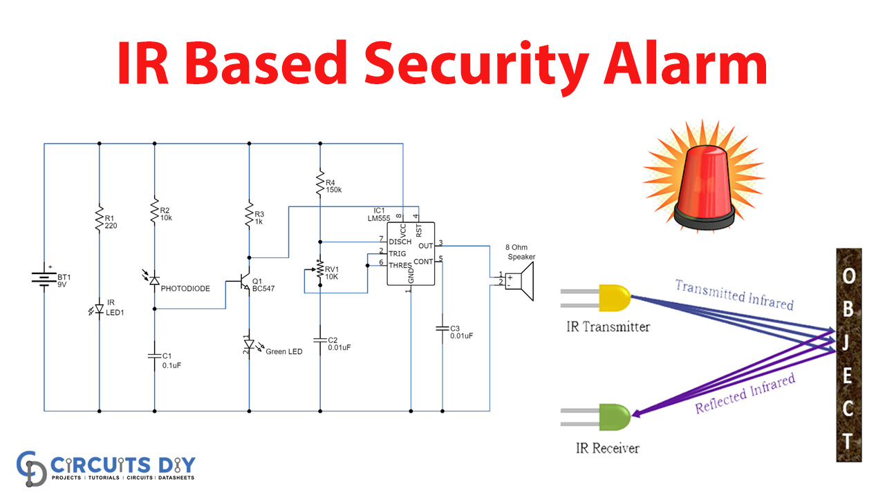
IR-based Security Alarm Circuit
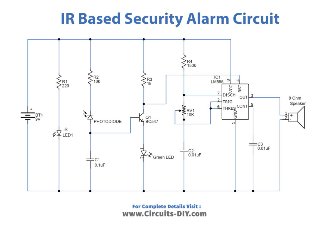
Working Explanation
The basic principle of this circuit is to detect any of the objects and generate a signal which made the buzzer beep. IR Led is used and connected to a 9v battery which continuously emits Infrared rays and these rays strike at the photodiode. (Note that IR led and photodiode must be positioned properly at the line of sight with each other, so infrared rays can fall directly on the photodiode). The photodiode conducts a current that turns on the transistor and the reset pin of the 555 timers C is connected to the ground which resets its output.
Now if any object comes in between IR led and photodiode, the photodiode stops conducting and the transistor switches off. This makes the reset pin of the 555 timers connected to the positive supply. As soon as the reset pin receives a positive supply it starts generating its output and the buzzer starts beeping.
The ON and OFF timing of the buzzer can be adjusted by varying the value of the Variable resistor and capacitor C2.
Applications:
- This circuit can be used in our homes and offices which we have designated as no-go areas or restricted areas.
- It can be used to alert if there is any movement around the location it is placed.