Most of the time it happens our kid opens the door of the fridge and left it open So In this electronics project, we are going to make a “Fridge Door Alarm Circuit” using a 555 timer ic and LDR. The name of the circuit itself presumes the application. This circuit triggers the alarm if it finds the refrigerator door left open for a long time.

Hardware Components
The following components are required to make Fridge Door Alarm Circuit
| S.No | Component | Value | Qty |
|---|---|---|---|
| 1. | Breadboard | – | 1 |
| 2. | Battery | 9v | 1 |
| 3. | Electrolytic Capacitor | 47uF | 1 |
| 4. | IC | NE555 Timer | 2 |
| 5. | LDR | – | 1 |
| 6. | Buzzer | – | 1 |
| 7. | Resistors | 100, 10k, 150k, 470k | 1,1,1,2 |
| 8. | Ceramic Capacitor | 0.1uF | 1 |
555 IC Pinout

For a detailed description of pinout, dimension features, and specifications download the datasheet of 555 Timer
Fridge Door Alarm Circuit
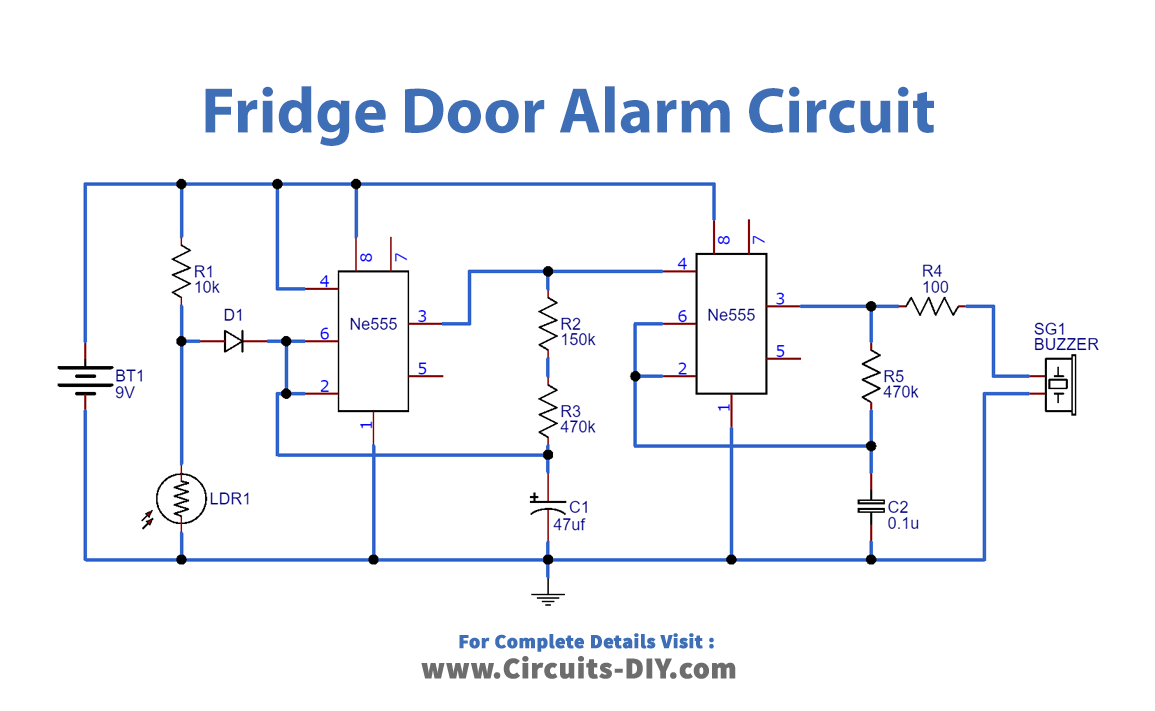
Working Explanation
The 9V battery powers the entire circuit. When the refrigerator door is not open, it is dark, and the resistance of the LDR is almost 1MὨ, as shown in the datasheet. The output voltage of the divider appears across the capacitor and remains in the state of charge (voltage higher than 2/3V VCC) making the output LOW. When we open the refrigerator, the light falls on LDR, which reduces the resistance of LDR and causes the capacitor to discharge, which in the RC combination is 30 seconds.
After this (voltage below 2/3 VCC), the output oscillates at a specific frequency with high output. Again, the capacitor charges and leads to a threshold pursued by the discharge of the capacitor. It continues until the LDR resistance goes up, which will happen in the absence of light.
It makes the second 555 timer oscillate, whose output goes HIGH and LOW causing the ring connected to the output to beep in a pattern that is a combinational source of the first-timer vibrations and the second-timer internal vibration. During the HIGH status of the first timer output, the second timer master reset will happen.
Thus, capacitor C2 charges (Voltage higher than 2/3V VCC) and the output goes LOW. In a short time, the capacitor discharges (voltage below 2/3V VCC) causing a high output. Hence, the sound signal connected to the output becomes an audible pulsed signal.