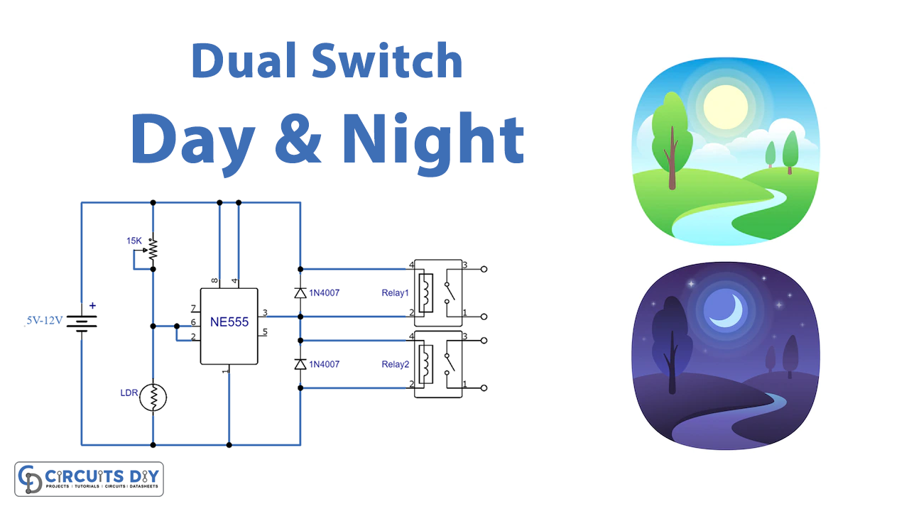
Dual Day and Night Switch is a sensor-based project that serves both day and night. IC NE555, an LDR and relay switch makes up the dual night and day switch circuit.
Hardware Required
| S.no | Component | Value | Qty |
|---|---|---|---|
| 1. | IC | NE555 Timer | 1 |
| 2. | LDR | – | 1 |
| 3. | Diode | 1N4007 | 2 |
| 4. | Variable Resistor | 15KΩ | 1 |
| 5. | Relay | – | 2 |
| 6. | Battery | 5V-12V | 1 |
Circuit Diagram
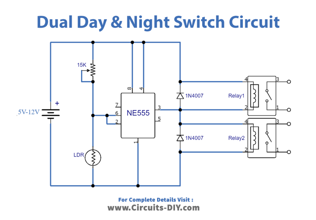
Circuit Explanation
This circuit incorporates an IC NE555 which is a timer IC. The timer IC produces clocks of desired timings set through a 15KΩ resistor. Hence, the day and night configuration actually depends upon the preset value of the 15KΩ resistor. An LDR is placed in the circuit that detects whether it is day or night in the room or the area placed.
During day time, the signal detected by the LDR is taken as the input to the IC NE555. Thus, NE555 activates relay 1 for daytime operation. Similarly, at night time, LDR accordingly sends the signal to the input of IC NE555 and thus relay 2 is activated. Therefore, electronic circuits connected to relays 1 and 2 work accordingly. furthermore, the diodes 1N4007 are responsible to stop polarity change in the circuit.
The operating voltage of the circuit is 5V to 10V. Also, the relays are selected so that they have the same voltage rating as that of the operating voltage of the circuit.