Introduction
Binary counters have a vast range of applications in electronic devices. They are used in circuits for timing operations and used to generate clock signals. As the name recommends, it is an electronic device or circuit which counts. The primary reason for the counter is to record the number of pulses coming. Ordinarily binary counters are utilized for counting the signal pulses coming from the input side at a particular period. These binary counters always need a memory because it needs to recall their previous states. So, we have decided that in this tutorial, we are going to “Binary Counter Circuit Diagram”.
The circuit needs two major elements as its key components, first the 555 timer IC and second the counter IC. Thus we are using HD74HC4040 as our counter. So, before starting let us see the features of HD74HC4040.

Hardware Required
The following components are required to make Binary Counter Circuit
| Sr.No | Component | Value | Qty |
|---|---|---|---|
| 1 | IC | 74HC4040 | 1 |
| 2 | IC | NE555 Timer | 1 |
| 3 | LED | – | 8 |
| 4 | Electrolyte Capacitor | 10uF | 2 |
| 5 | Resistor | 1KΩ, 10KΩ, 220Ω | 2,1,1 |
| 6 | Connecting wires | – | – |
| 7 | Battery | 9V | 1 |
| 8 | 2-Pin Connector | – | 2 |
| 9 | Ceramic Capacitor | 0.1uF | 1 |
NE555 IC Pinout

For a detailed description of pinout, dimension features, and specifications download the datasheet of 555 Timer
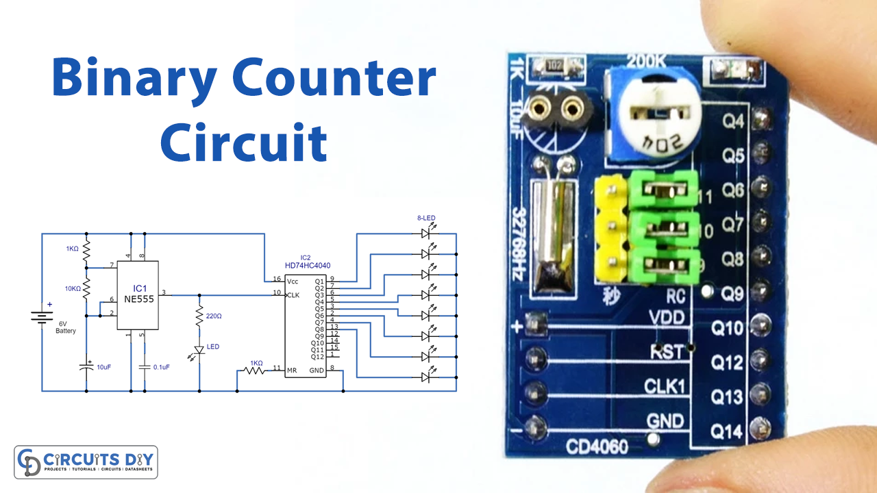
Binary Counter Circuit
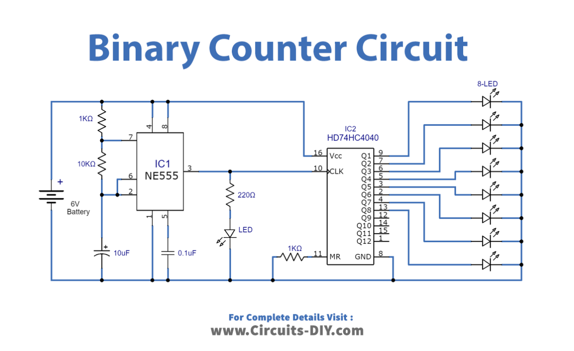
Working Explanation
In this Binary Counter Circuit, the IC 555 is wired as an astable multivibrator that triggers the counter HD74HC4040. When the clock input is given to pin 10 ( i.e, clock pin). We can vary the output pulse by changing the resistance of R2. LEd is there in the circuit to indicate the status of pulses coming from 555. The pulse is given to the counter HD74HC4040 through the input clock pin. At each pulse, it increases the count value and gives it to the output pins. 8 LEDs are connected here in our circuits at 8 out of 12 output pins. The turning On of any LED shows binary 1 and off shows binary OFF.
Application and Uses
- Digital clocks.
- Frequency counters also utilize this circuit.
- To generate clock signals in various circuits.