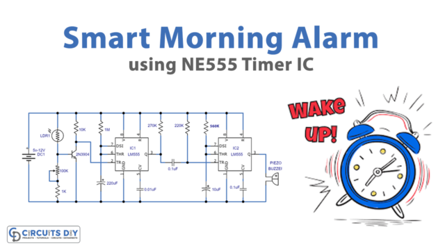
In this tutorial, we are going to design a Simple Doorbell circuit using a 555 Timer IC. It is a very common and useful device. Almost everyone uses it. The main feature of this doorbell circuit is that we can control its time duration. So it keeps on ringing as the switch or button is pressed.
The 555 Timer IC controls the oscillation frequency of the doorbell sound. Every doorbell produces different types of sound depending on its functionality.

Hardware Components
The following components are required to make Doorbell Circuit
| S.No | Component | Value | Qty |
|---|---|---|---|
| 1. | Breadboard | – | 1 |
| 2. | Battery | 9v | 1 |
| 3. | Connecting Wires | – | 1 |
| 4. | IC | NE555 Timer | 2 |
| 5. | Variable Resistor | 10k | 1 |
| 6. | Resistors | 1k, 10k, 100k | 1, 1, 1 |
| 7. | Capacitor | 1000uF, 1uF | 1, 1 |
| 8. | Buzzer | – | 1 |
| 9. | Push Button | – | 1 |
555 IC Pinout

For a detailed description of pinout, dimension features, and specifications download the datasheet of 555 Timer
Doorbell Circuit Diagram
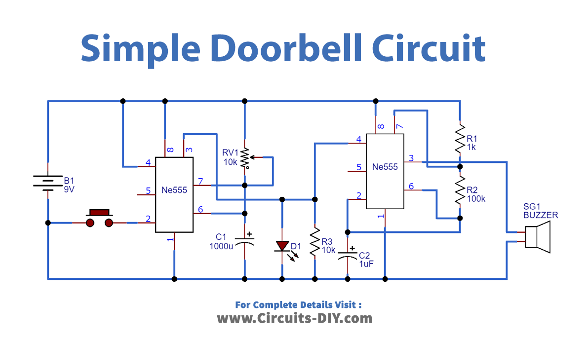
Working Explanation
The Doorbell circuit consists of two 555 Timer ICs. One IC controls the ring duration and the other IC controls the oscillation frequency of the sound produced by the bell. The first-timer IC operates in monostable mode. And the second timer IC operates in astable mode. In this way, the first-timer IC modulates the frequency of the second-timer IC. In order to control the ring duration, an output of the first-timer IC is connected to the reset pin of the second-timer IC. This means that as long as the output of the first-timer IC is high the second IC oscillates. There is a difference between the astable mode and the monostable mode. An astable mode is free running and it does not require any external triggering. This has no stable state. Whereas monostable requires triggering for high and low.
Application
- This circuit has many applications in houses, restaurants for serving, hospitals, and several other places.