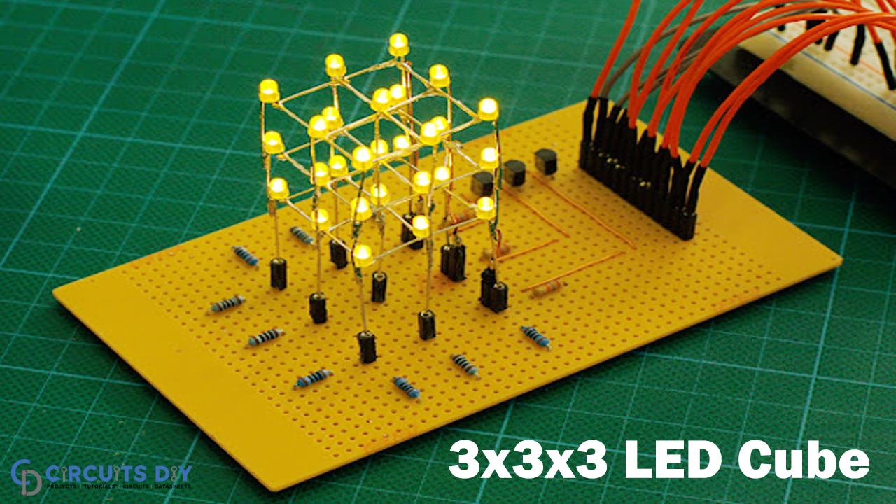
Today we have come up with another astounding DIY circuit “3x3x3 LED Cube” by using NE555 timer IC along with CD4060. Generally, an LED Cube is built by utilizing some microcontrollers like Arduino or Raspberry Pi. However, the primary fantasy in this circuit tutorial is that we will make a 3x3x3 LED Cube with no microcontroller just by utilizing two versatile ICs. Here we will use a 555 timer IC and CD4060 binary counter to control the LED Cube.
Generally, for controlling a LED CUBE, we use microcontrollers and programming for getting various coloring patterns. However, it’s a perplexing process for amateurs, so here we are utilizing the combination of 555 Timer and CD4060 IC, which is most appropriate for amateur learners. Meanwhile, we will only get one pattern here in this circuit, yet this is an ideal approach to getting acquainted with LED Cubes and their work.

Hardware Component
The following components are required to make the LED Cube Circuit
| S.no | Component | Value | Qty |
|---|---|---|---|
| 1. | IC | NE555 Timer | 1 |
| 2. | Resistor | 1K | 10 |
| 3. | Binary Counter IC | CD4060 | 1 |
| 4. | Variable Resistor | 10K | 1 |
| 5. | Capacitor | 10uF | 1 |
| 6. | Soldering Iron | – | 1 |
| 7. | LED | – | 27 |
| 8. | Battery | 5-9 V | 1 |
CD4060 Pinout
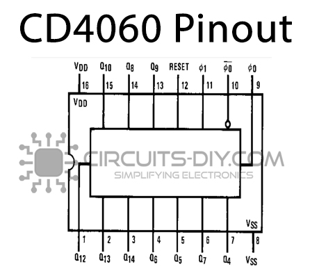
For a detailed description of pinout, dimension features, and specifications download the datasheet of CD4060
NE555 IC Pinout

For a detailed description of pinout, dimension features, and specifications download the datasheet of NE555 IC
LED Cube Circuit
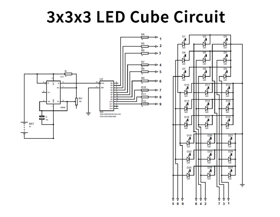
Working Explanation
As appears in the schematic above, we have an aggregate of 12 pins from the CUBE. Over which 9 Pins are Common Positive, and three pins are Common Negative Terminals. Meanwhile, every column represents a positive terminal, and each layer (row) represents a negative terminal.
Since we control the LED CUBE by CD4060 counter, there will be no control required at negative terminals. So we have grounded every one of the three standard negatives as appears in the circuit schematics. Thus, with this, we will have nine positive terminals from 9 columns of the LED cube.
Here the 555 chip creates a square wave for the LED to flip among ON and OFF states. The potentiometer utilizes here to change the frequency of squinting.
Furthermore, this square wave yield is fed into the binary counter chip. However, the binary counter tallies the clock pulses, and the counter further processes the number of pulses through Q0-Q13 pins. We will associate these counter yield pins to the LED CUBE sections as per circuit schematics.
So, in a nutshell, 555 pluses produce clock pulses, counter checks the clock pulses, and make its yield high relying upon the yield of CD4060. That is the way the 3x3x3 LED CUBE works.
Applications and Uses
It can be used in the home lighting system.