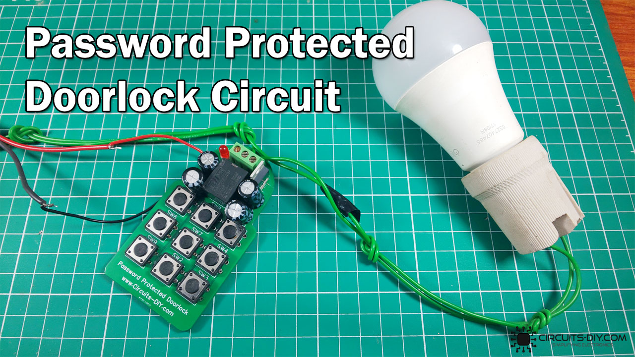
This is an intriguing DIY detailed instruction tutorial on “Electronic Door Lock Password Security Circuit” using IRF540 MOSFET. It can use as a security check system to constrain access to only certain people with security codes.
The fundamental standard of this circuit is that the door lock only opens when the switches in series are squeezed at a time. However, if any switch other than the password key switches is pressed, the circuit resets itself. Meanwhile, if the switches in series are pressed in order, the capacitor turned on the relay which consequently opens the electronic lock.
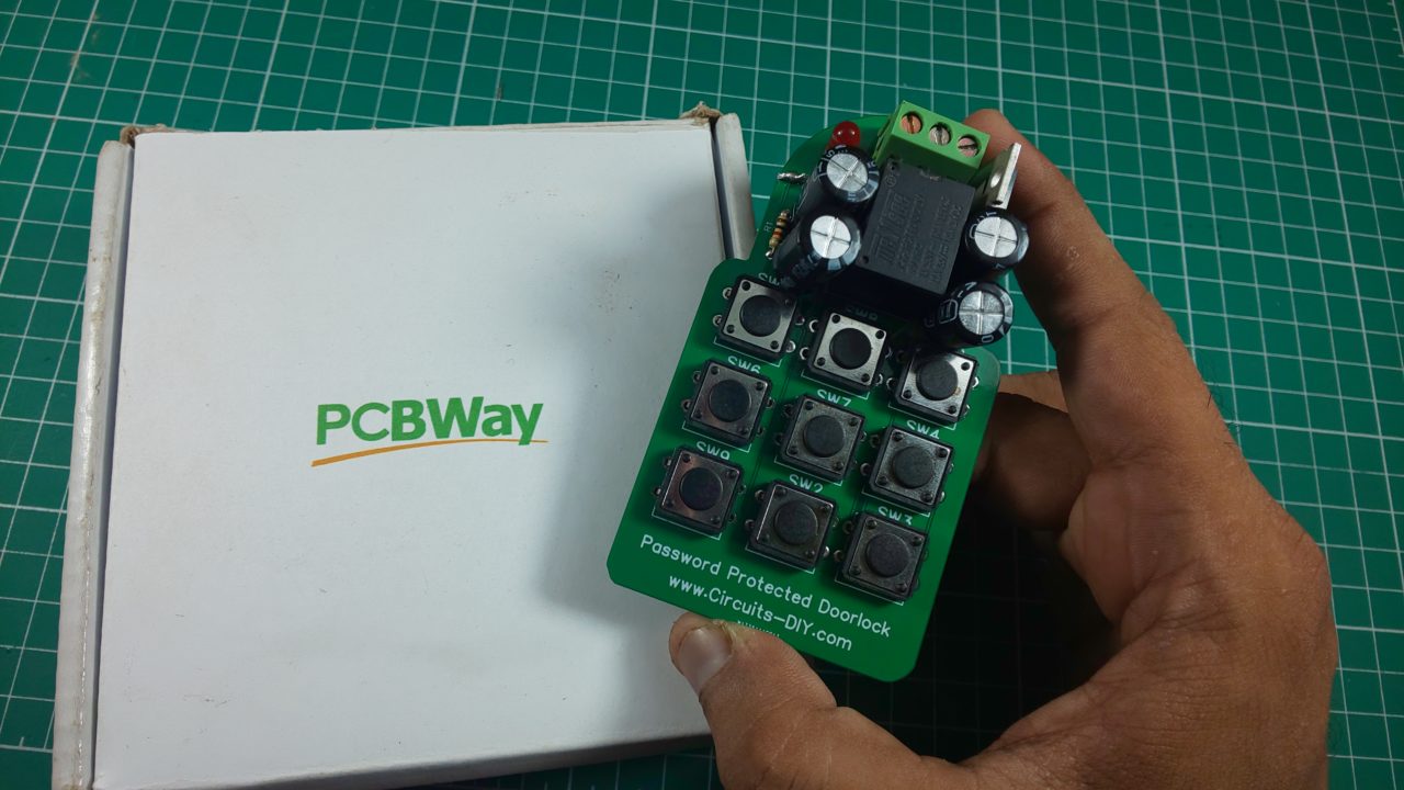
PCBWay commits to meeting the needs of its customers from different industries in terms of quality, delivery, cost-effectiveness, and any other demanding requests. As one of the most experienced PCB manufacturers in China. They pride themselves to be your best business partners as well as good friends in every aspect of your PCB needs.
Hardware Components
The following components are required to make Password Security Doorlock Circuit
| S.no | Component | Value | Qty |
|---|---|---|---|
| 1. | MOSFET | IRF540 | 1 |
| 2. | Diode | 1N4007 | 1 |
| 3. | Capacitor | 10V/470µF | 4 |
| 4. | Relay | 5V | 1 |
| 5. | Zero PCB | – | 1 |
| 6. | LED | – | 1 |
| 7. | Resistor | 470Ω | 1 |
| 8. | Switch | – | 9 |
| 9. | Battery | 9V – 12V | 1 |
IRF540 Pinout
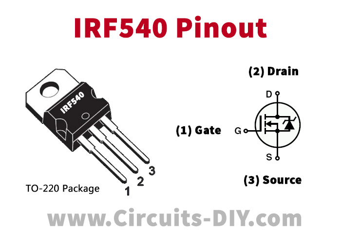
For a detailed description of pinout, dimension features, and specifications download the datasheet of IRF540
Password Security Doorlock Circuit

Working Explanation
The password security door lock circuit operates in a manner that, when I press the first switch, the first capacitor will take charge from the power source or battery. And when I press the second switch, the half charge of the first capacitor will transfer to the second capacitor. This cycle will run up to the last capacitor of the circuits. Hence, the fourth capacitor activates the 5V relay which consequently unlocks the electronic lock.
Applications and Uses
- It utilizes in security checking system
- Door locking