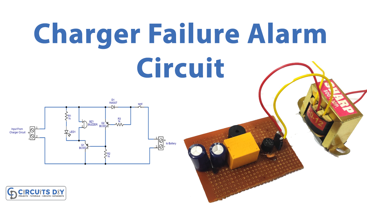
Introduction
Does that happen to you that you place your device for charging and someone removed the device to charge theirs? Does that make you angry? Because the time when you want the device to be fully charged is then not available because of less charging. To overcome this problem of disconnection of changing devices, we are here with some interesting circuits that give you an alert when the battery gets disconnected from the charger. Moreover, it also helps to indicate if the short circuit happens. For indication, we have used a buzzer at the load as output but with that, we have also used LED for visual indication. So, in this tutorial, we are going to Make a “Charger Circuit Failure Alarm”
Hardware Required
| S.no | Component | Value | Qty |
|---|---|---|---|
| 1. | Transistor | BC557 | 2 |
| 2. | SW_SPST | – | 1 |
| 3. | Buzzer | – | 1 |
| 4. | LED | – | 1 |
| 5. | Diode | 1N4007 | 1 |
| 6. | SMD Resistor | 1K, 10K | 2,1 |
| 7. | 2-Pin Connector | – | 2 |
Circuit Diagram
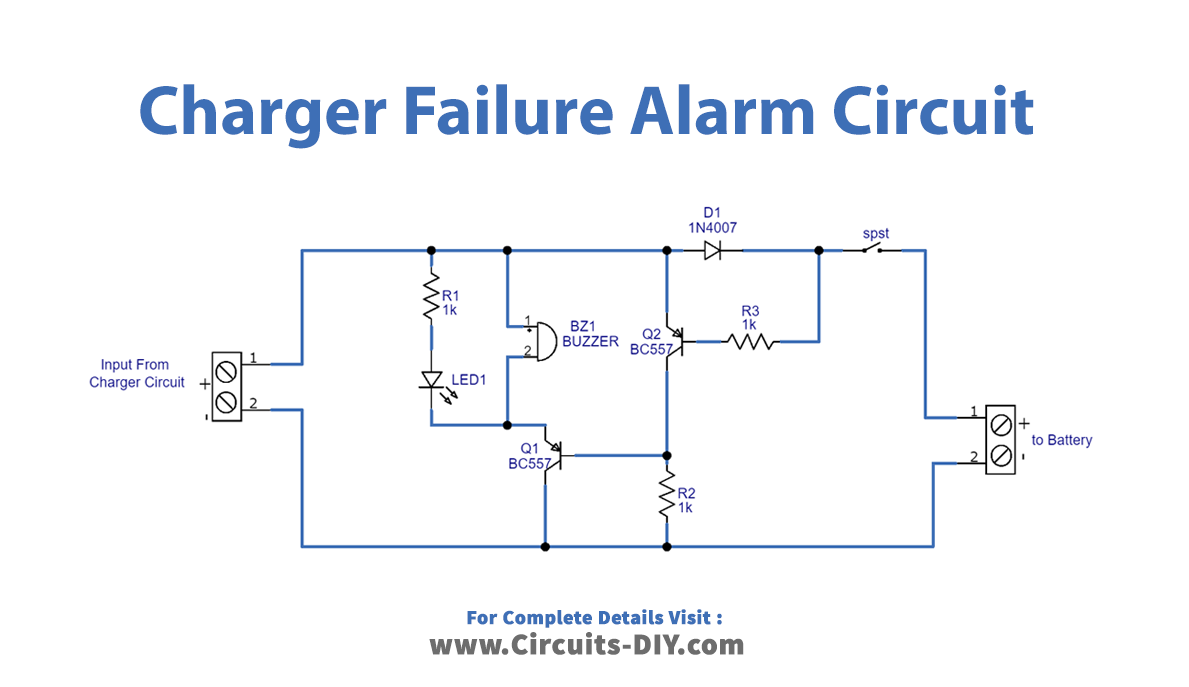
Working Explanation
To make the charger circuit failure alarm, connect the circuit according to the given circuit diagram. The circuit is basically wired between the charger and the charging battery. The SPST switch is open while the battery is connected to the charger. Now, if the disconnection happens between the charger and the battery, or if a short circuit happens, the switch gets closed at the base of the BC557 transistor which is working as a switch in this circuit. Diode D2 is there to prevent the circuit from reverse polarity. The collector of transistor Q2 is connected to the base of the other transistor and the emitter got connected to the buzzer. Both the transistor helps is there to connect the buzzer to the bias. buzzer and LED are working as a load of this circuit.
Application and Uses
- To indicate the disconnection between the charger and the battery.
- To help in the indication of short circuits.