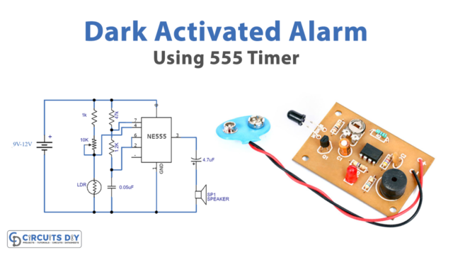
Here, we are going to make a project of a simple circuit called the “panic alarm button.” A “Panic Alarm Circuit” is utilized to impart an emergency signal promptly to the individuals in close-by areas to call for help or to caution them. The conceivable frenzy circumstance can be any; it isn’t confined to scarcely any circumstances.
One might keep the press button at their reachable distance or at a nearby spot to do quick action without the noise of pressing the button. The sign of emergency can either be an “audible or visible” sign, fixed a couple of meters away through a wire.

Hardware Component
The following components are required to make Panic Button Alarm Circuit
| S.no | Component | Value | Qty |
|---|---|---|---|
| 1. | IC | NE555 timer | 1 |
| 2. | Resistor | 1K, 10K | 2, 2 |
| 3. | Capacitor | 0.01uF | 1 |
| 4. | Tactile switch | – | 2 |
| 5. | Transistor | BC547 | 1 |
| 6. | LED | – | 1 |
| 7. | Battery | 9V | 1 |
NE555 Pinout

For a detailed description of pinout, dimension features, and specifications download the datasheet of 555 Timer
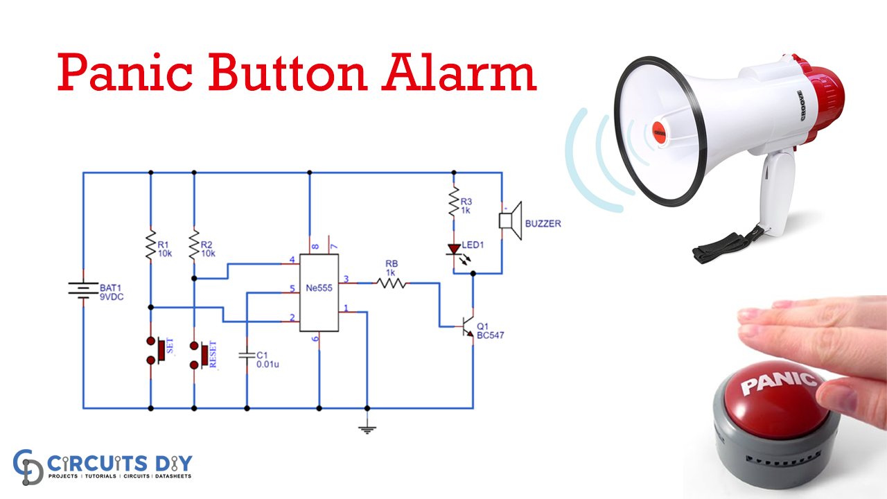
Panic Button Alarm Circuit
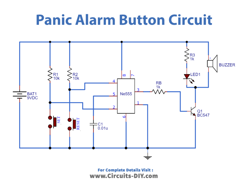
Circuit Operation
In this circuit, we use a few low-cost components, including a 555 timer IC, a ceramic capacitor, resistors, a 9 V battery, an LED, a tactile switch, a buzzer, and a transistor. First, you have to press the reset pin 4, and pin 2 becomes low, which makes the comparator becomes low. And the flip flop and output become high. The process of resetting the 555 timers is done by pressing the RESET button.
Then the flip flop and output become low. As we know that the NPN transistor is a current-controlled element. When the output reaches the base of the transistor, the transistor becomes On, and the LED and buzzer also turn ON.
Applications and Uses
This Panic Alarm Button Circuit is used when someone is in an emergency and wants to call someone for help.