The LED Flasher circuit outputs a Flip Flop manner LED blinking. The circuit uses NE555 timer IC along with a bridge rectifier to rectify the AC main supply.

Hardware Components
The following components are required to make LED Flasher Circuit
| S.no | Component | Value | Qty |
|---|---|---|---|
| 1. | AC power supply | – | 1 |
| 2. | IC | NE555 Timer | 1 |
| 3. | Diode | 1N4007 | 4 |
| 4. | Zener Diode | 12V/1W | 1 |
| 5. | LEDs | – | 12 |
| 6. | Resistor | 62Ω, 10KΩ, 1MΩ/1W | 4,1 |
| 7. | Variable resistor | 100KΩ | 1 |
| 8. | Electrolytic capacitor | 330µF/25V, 10µF | 1,1 |
| 9. | Ceramic Capacitor | 330nF/400V, 0.01µF | 1,1 |
NE555 IC Pinout

For a detailed description of pinout, dimension features, and specifications download the datasheet of 555 Timer
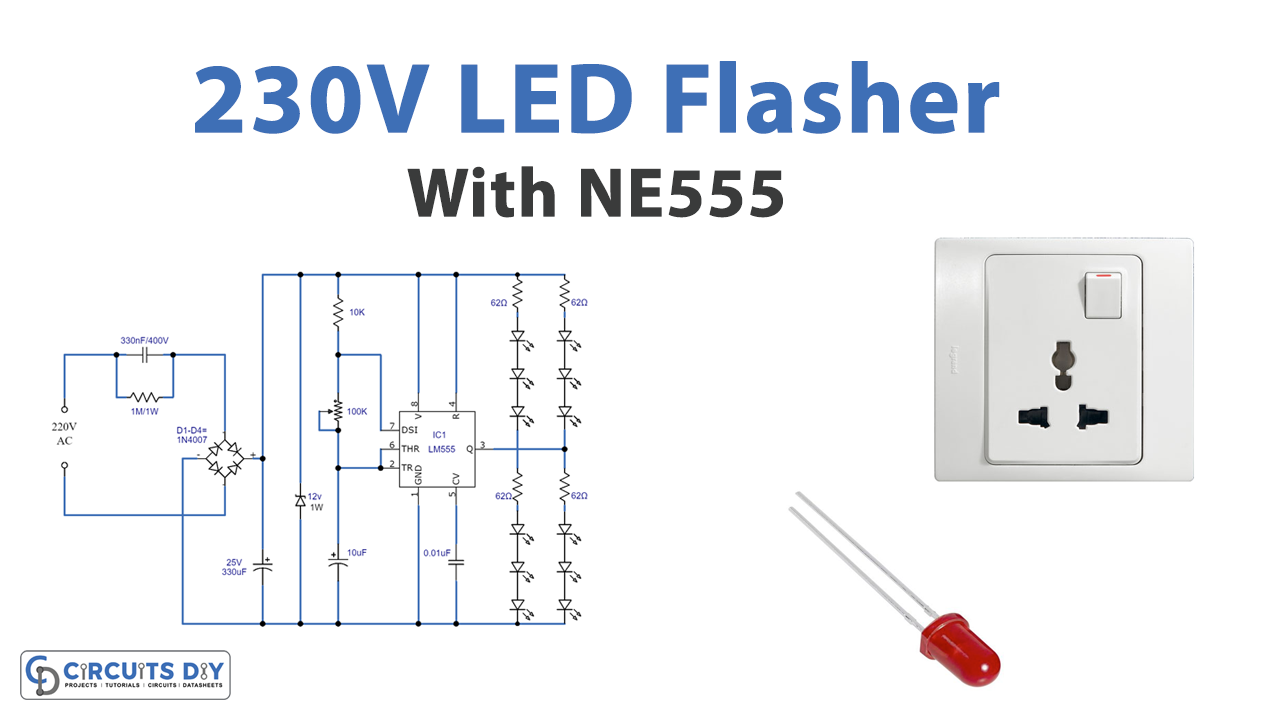
LED Flasher Circuit
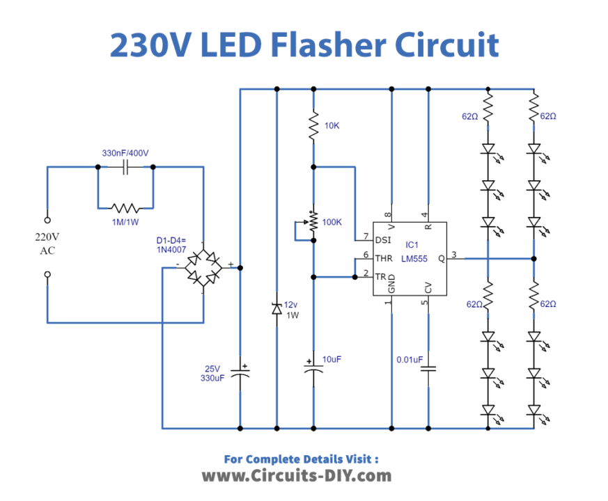
Working Explanation
In this circuit, the power supply is directly taken from the AC main. The voltage from AC main is stepped down using a capacitor of 330nF.
Furthermore, four diodes 1N4007 are connected as a bridge rectifier that rectifies the low voltage signal coming from the capacitor. Moreover, a 330µF electrolytic capacitor further filters this signal and sent it to the Zener diode. The Zener diode limits the rectified and filtered voltage to 12V to operate the IC NE555.
Now, the LED flasher circuit includes the timer IC NE555 and a dozen of LEDs. NE555 timer IC works in its astable multivibrator mode where it generates regular rectangular pulses of set time duration. In this case, the LEDs operate in a Flip Flop manner that is blinking ON/OFF for a specific time duration. Also, a 100KΩ variable resistor, connected with the PIN06 and PIN02 of IC, controls the blinking speed or the ON/OFF time duration of LEDs.
Extra care is required while handling the project as it is working with the main AC supply.
Application
- Event lighting system
- Home decoration