Nowadays, the IR sensor is a widely used electrical sensor in security and other applications. Meanwhile, an IR sensor comprises an IR LED and photodiode, in which IR LED emits IR radiation and the photodiode distinguishes the radiation. Photodiode conducts current in invert direction, whenever the light falls on it, along with changing the voltage across it. Furthermore, this voltage change is detected by a voltage comparator (like LM358) and produces a yield likewise.
Therefore, in this IR-based security alarm circuit, we have set IR LED before the photodiode, so IR light can fall on the photodiode. Hence, whenever somebody travels in front of this sensor circuit, the IR beams quit falling on the photodiode and the Buzzer begins to ring. In addition, the buzzer automatically stops after some time, as the bell is associated with the 555 timer IC in a monostable mode in this circuit.
Hardware Components
The following components are required to make IR Security Alarm Circuit
| S.no | Component | Value | Qty |
|---|---|---|---|
| 1. | IR pair (IR LED and Photodiode) | – | 1 |
| 2. | IC | NE555 timer | 1 |
| 3. | Resistor | 10K, 100K, (100,220,330) ohm | 1 |
| 4. | Variable resistor | 10K | 1 |
| 5. | Capacitor | 10uF | 1 |
| 6. | Buzzer | – | 1 |
| 7. | IC | LM358 | 1 |
LM358 Pinout

For a detailed description of pinout, dimension features, and specifications download the datasheet of LM358
NE555 IC Pinout

For a detailed description of pinout, dimension features, and specifications download the datasheet of NE555 IC
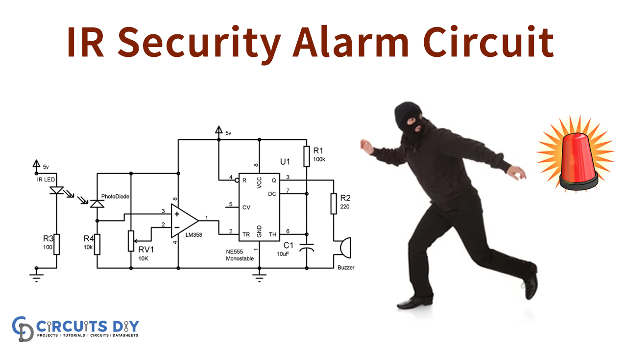
IR Security Alarm Circuit
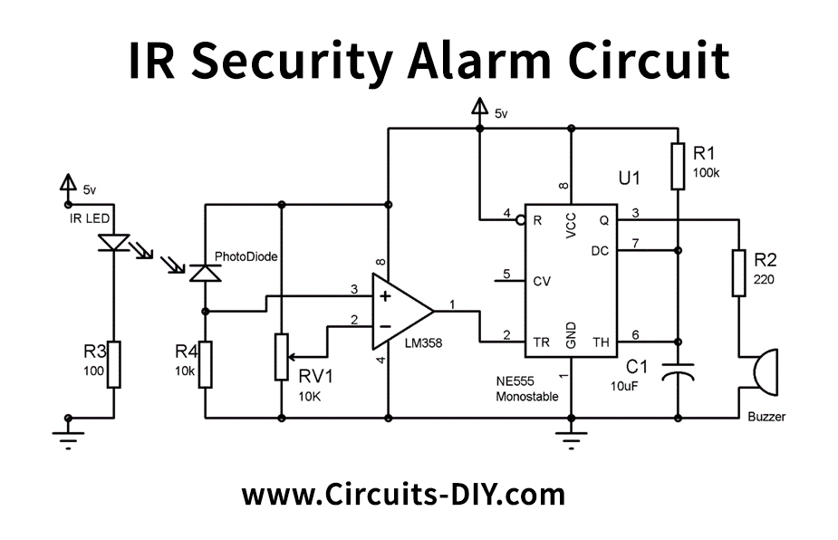
Working Explanation
Here in this circuit, we are using an op-amp LM358. Meanwhile, this LM358 has two voltage comparators inside it, but we use only one comparator here. However, the non-inverting end (PIN3) of the voltage comparator is associated with the Photodiode. Moreover, the inverting end (PIN 2) of the voltage comparator associate with a variable resistor of 10 K. The yield of the voltage comparator (PIN1) transfers to the Trigger pin of the 555 timer IC. Hence, because of these features, the 555 Timer IC design is here in monostable mode.
While the IR radiation is falling on Photodiode, the voltage at the non-inverting end (+) of the voltage comparator is higher than the inverting end (-) and the yield of the comparator is HIGH. Also, as the comparator yield is associated with the trigger PIN of the 555 timer IC when Trigger pin 2 is high, the 555 yield is low. So during the period when the IR beams fall on Photodiode, the 555 yield stays LOW.
Therefore, when there is some movement, the falling of IR beams on the Photodiode gets hindered and the voltage at the inverting end (Threshold voltage) of the voltage comparator gets higher than the non-inverting end. This makes the yield of the comparator LOW and furthermore makes the Trigger PIN 2 of 555 timer LOW. Additionally, it will further trigger the 555 timer IC, and 555 OUTPUT goes HIGH and Buzzer rings for brief spans.
Applications and Uses
- Use in prohibited areas