Introduction
The significant principle of a light-activated alarm using a 555 timer is to generate sound that depends on the intensity of light that falls on the circuit. As the intensity of light that is fallen on the circuit is increased, it generates pulses for a longer period and hence it generates more sound.
The foremost part of the circuit is based on the Integrated circuit (IC) named 555 timers. This circuit generates oscillation that depends on the intensity of light of the Light Dependent Resistor.
Hardware Required
| S.no | Component | Value | Qty |
|---|---|---|---|
| 1. | IC | NE555 Timer | 1 |
| 2. | Light Dependent Resistor (LDR) | of any size | 1 |
| 3. | Speaker | 8 ohm | 1 |
| 4. | Variable resistor | 10K or 1M | 1 |
| 5. | Resistor | 1.2K, 47K, 1K | 1,1,1 |
| 6. | Capacitor | 47uF, 0.05uF | 1,1 |
| 7. | DC Supply | 9-volt to 12 volt | 1 |
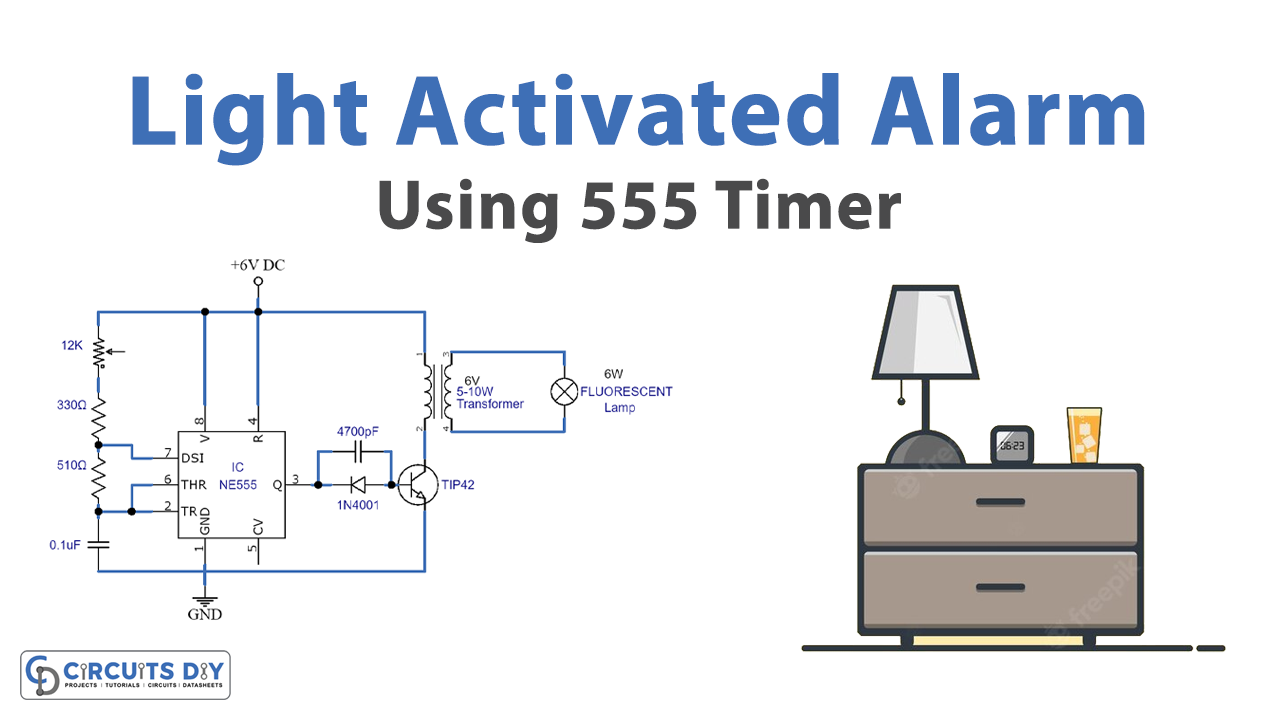
Circuit Diagram
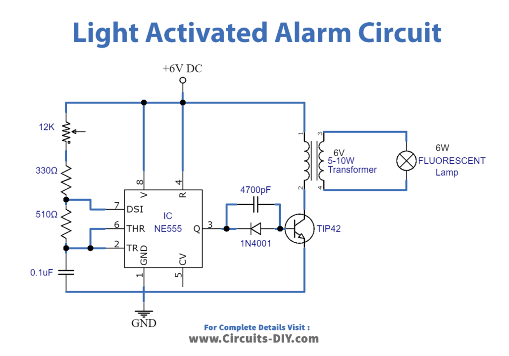
Working Explanation
The circuit of the light-activated alarm using 555 timer IC generates sound when the light falls on the outward side of light Dependent Resistor (LDR). A significant part of the circuit is the 555 timer IC that is connected to the circuit as a multi-stable vibrator. An LDR is used as a sensor of light. A variable resistor of 10k is used to regulate the sensitivity of the circuit. A speaker of 8 ohms is used to give output in the form of sound. By altering the value of the capacitor of 0.05 microfarad, the frequency of the sound is changed. The circuit operates at the DC voltage of 9 volts to 12 volts.
Application and Uses
- The circuit is used in signals of emergency.
- The circuit is used in the sirens of civil defense to deliver warnings during natural disasters.