
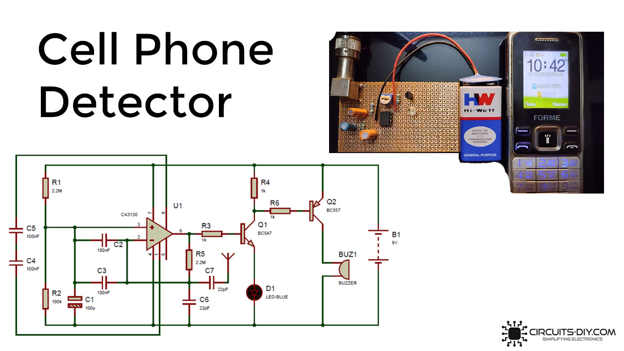
In this tutorial, we will show the construction of the Cell Phone Detector circuit. Generally, this detector can recognize the existence of any mobile phone that is activated nearby, indicating an indicator of the mobile phone that is accessed around it. The cell phone detector is a frequency detector or a give that captures the frequency bands between 0.8 and 3.0 GHz (Mobile band frequencies). RL adjusted to meet (Resistor–Inductor circuit) does not detect GigaHertz RF signals.
In other words, Incoming/outgoing phone calls, Facebook messenger, video clips, and any Notification or GPRS frameworks in the range of 1 meter can be reported in this Mobile Detector Circus. Cell phones in mobile areas such as halls of residence, lecture halls, healthcare facilities, etc., are useful to detect this circuit. It can also be used to detect illegal use or to spy on concealed cell phones. The RF transmission can be seen from your mobile telephone, causing Buzzer to generate beep sounds, even if the phone is in silent mode, and this warning continues until RF signals are readily accessible.
Hardware Component
The following components are required to make Cell Phone Detector circuit
| S.no | Component | Value | Qty |
|---|---|---|---|
| 1. | Connecting wires | – | – |
| 2. | Transistor | BC557, BC547 | 1,1 |
| 3. | Electrolyte Capacitor | 100uF | 1 |
| 4. | LED | – | 1 |
| 5. | Battery Connector | – | 1 |
| 6. | Battery | 9 Volt | 1 |
| 7. | Breadboard | – | 1 |
| 8. | Buzzer | – | 1 |
| 9. | Antenna | – | 1 |
| 10. | Op-Amp IC | CA3130 | 1 |
| 11. | Resistor | 1K,100K,2.2M | 2,1,1 |
| 12. | Ceramic capacitor | 22pF, 100nF | 2, 3 |
CA3130 Pinout

For a detailed description of pinout, dimension features, and specifications download the datasheet of CA3130
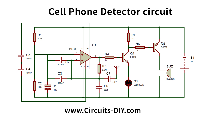
Cell Phone Detector circuit
Working Explanation
Here we used the CA3130 OP-Amp IC throughout this circuit for inlet and outlet detection around it. The non-inverting Vcc end of the optical amplifier is connected with a 2.2M resistor and associated with the ground by a 100K resistor and 100uF Capacitor. Its inverting terminal is a 2.2M resistor feedback from its output, which amplifies the signal. The respondents represent a loop antenna with two 100nF condensers attached between inverted and non-inverted terminals. In the connection between pin 1 and 8 of the op-amp, two 100nF condensers are mounted to enhance the voltage regulator’s quality increase at the electric motor.
At the base of the NPN transistor, namely the BC547, this sensor is attached by way of even a 1k resistor, and an LED is mounted at its transmitter. A smoke detector is also used with the PNP transistor BC557 for sound evidence. For powering the circuit, a 9-volt battery is used. The residual traces are shown in the Schematic Diagram.
Applications and Uses
In test centers and workshops on detecting mobile phones and avoiding cellular use, this circuit can be used. It can be used to trace digital devices used to spy and illegal audio and video transmission.
Related posts:
 Four-Way Traffic Light Circuit Using 555 Timer IC
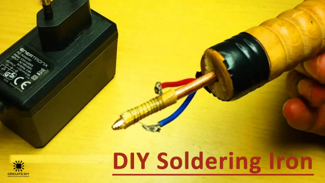 DIY 12 Volt Soldering Iron - Homemade
 5 Volt USB Mobile / Car Charger using LM7805 - DIY Project
 Temperature Controlled DC Fan - Electronics Projects
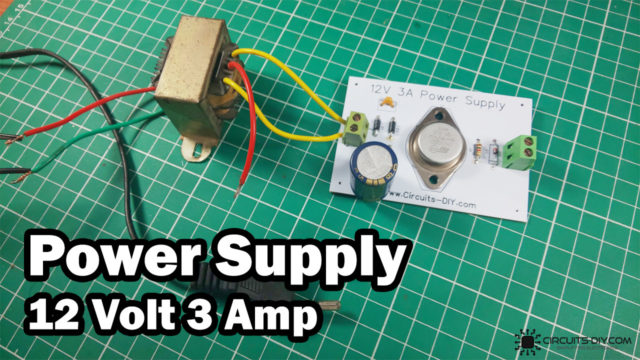 How to make 12 Volt 3 Ampere Power Supply - DIY
 Heartbeat Sensor Circuit Using LM358 - Electronics Projects


