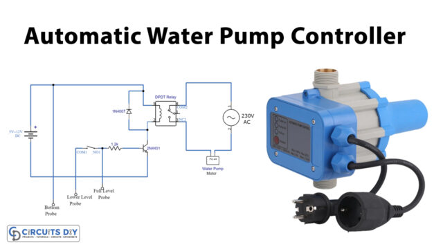
In this tutorial, we will design the four-way traffic light project circuit. Traffic light signal plays an important role to control vehicles on the road. The four-way traffic light uses a 555 Timer IC and a counter IC CD4017.
The 555 Timer IC operates as an astable multivibrator. It produces a pulse that depends on the timing of the resistor and capacitor. The pulses are then fed into the clock input of the counter IC. This changes the output logic into HIGH or LOW. By connecting the proper color LED at the output of the counter IC traffic light signal is obtained.

Hardware Components
The following components are required to make Traffic Light Circuit
| S.NO | Component | Value | Qty |
|---|---|---|---|
| 1. | Breadboard | – | 1 |
| 2. | Battery | 9v | 1 |
| 3. | Connecting Wires | – | 1 |
| 4. | IC | NE555 Timer | 1 |
| 5. | Decade Counter IC | CD4017 | 1 |
| 6. | Diode | 1N4007 | 8 |
| 7. | Resistor | 1KΩ, 10KΩ, 220Ω | 1, 1, 3 |
| 8. | Electrolytic Capacitors | 10µF, 100µF | 1,1 |
| 9. | LED | 5mm | 10 |
555 IC Pinout

For a detailed description of pinout, dimension features, and specifications download the datasheet of 555 Timer
CD4017 Pinout
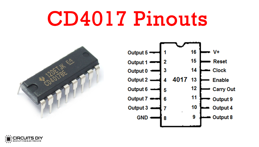
For a detailed description of pinout, dimension features, and specifications download the datasheet of CD4017
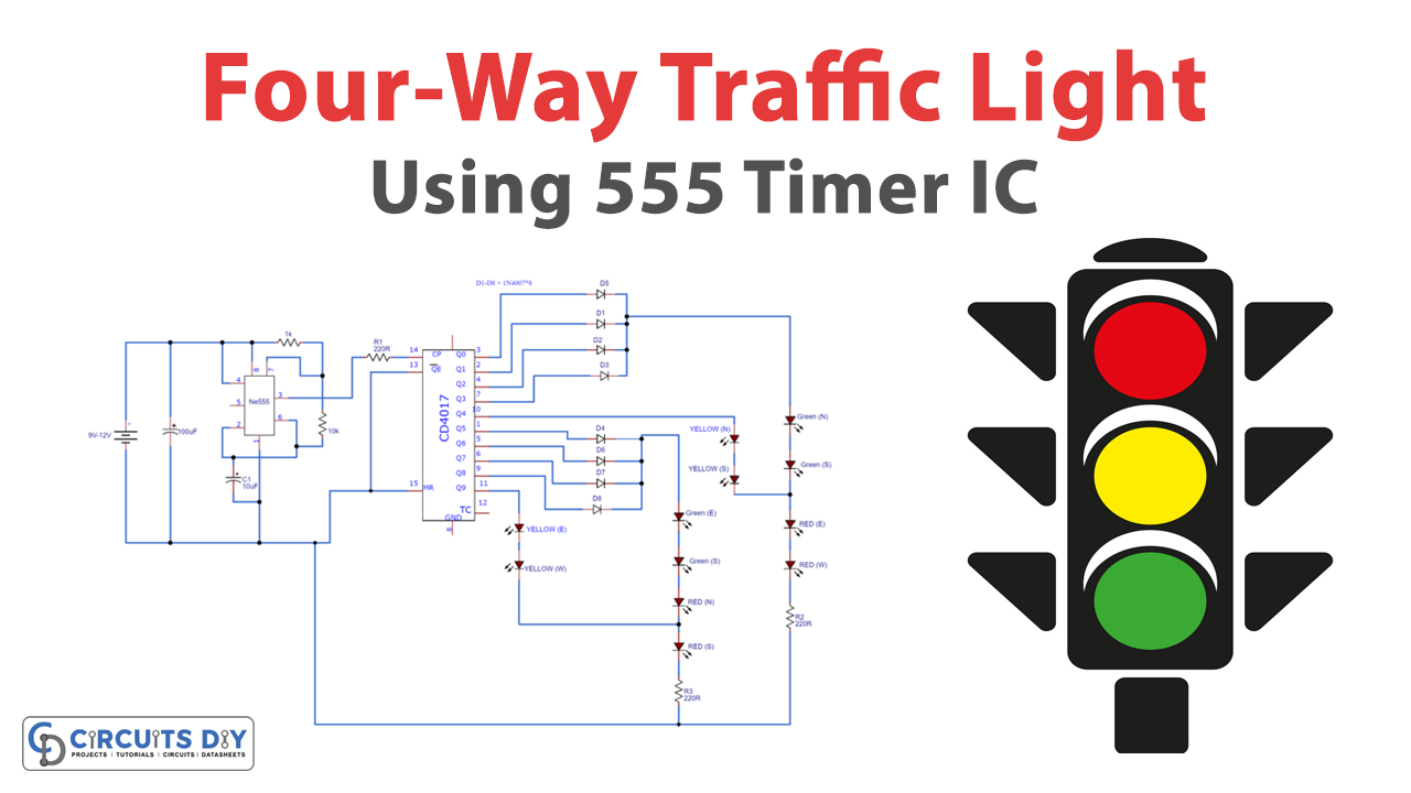
Traffic Light Circuit
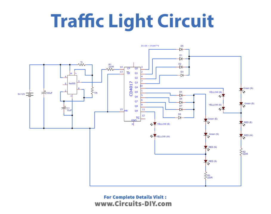
Working Explanation
The four-way traffic light circuit consists of two stages. The first one is the timing and counting stages. The other one is an indication of the light stage. The indication of the light stage should be properly placed on four lanes. The values of the capacitor and the resistor set the timing of the 555 IC. It then delivers them at the output pin. These pulses decide the timing interval of traffic light signals. The decade counter IC has ten outputs. Q0 to Q3 will drive a green signal for the north and south lanes, and a red signal for the east and west lanes. The output Q4 drives a yellow signal for the north and south lanes. Then the output from Q5 to Q8 will drive a green signal for the east and west lane, Red signal for the north and south lanes. An output Q9 drives a yellow signal for an east and west lane.
Application
- This project has greater application and importance to control and regulate vehicles and traffic on heavy traffic roads.