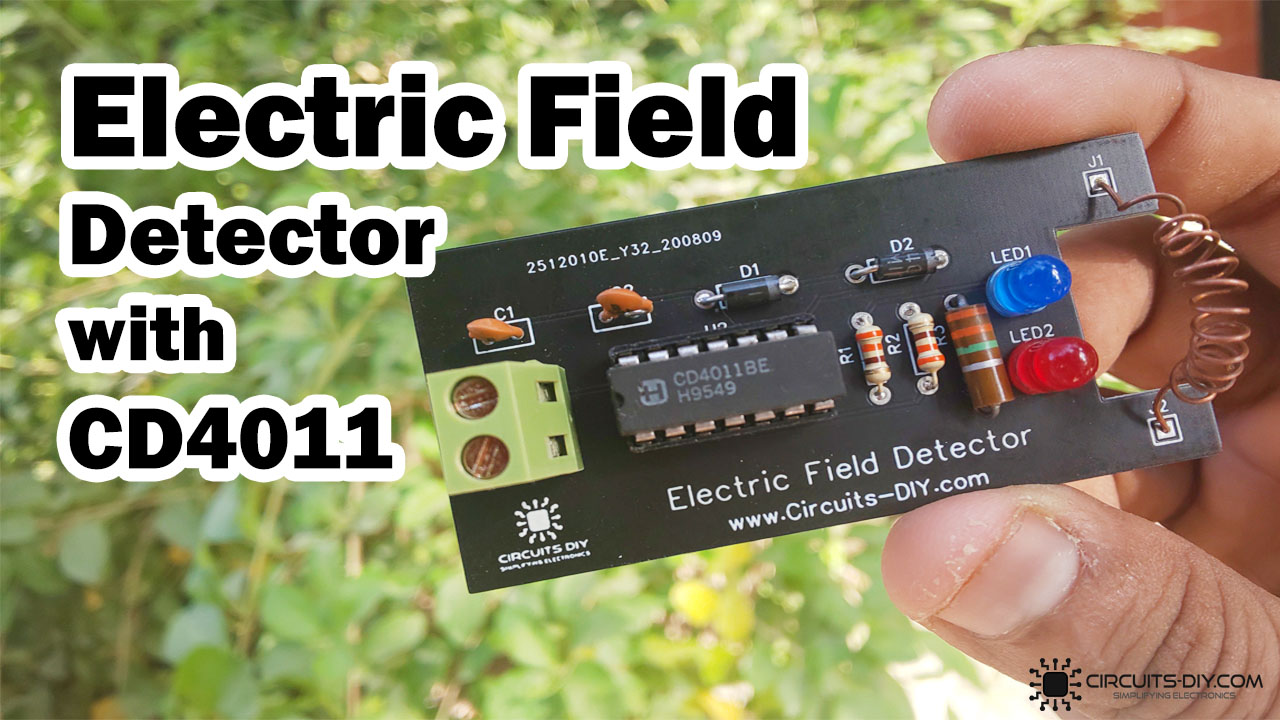
What is an Electric Field Detector?
A Static Electric field strength detector or just an Electric field detector is an electronic device capable of sensing the presence of any static electrical field within its vicinity. They serve as a useful safety tool to remotely identify whether the housing of any industrial equipment is charged due to a damaged earth connection. So in this tutorial, we will look into the process of making an Electric Field Detector using CD40117BE IC
The heart of this circuit is a CD40117BE a dual 4-bit terminator IC. It can be programmed by means of STROBE and DATA control bits to function as pull-up or pull-down resistors. The CD40117BE can also be programmed to function as latches to terminate any open or unused CMOS logic
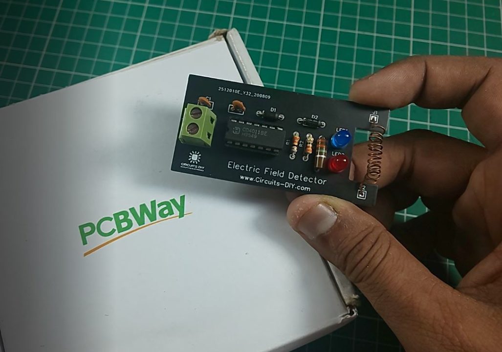
PCBWay commits to meeting the needs of its customers from different industries in terms of quality, delivery, cost-effectiveness, and any other demanding requests. As one of the most experienced PCB manufacturers in China. They pride themselves to be your best business partners as well as good friends in every aspect of your PCB needs.
Hardware Components
The following components are required to make Electric Field Detector Circuit
| S.no | Component | Value | Qty |
|---|---|---|---|
| 1. | Terminator IC | CD4011BE | 1 |
| 2. | enameled copper wire | 12 AWG | 1 meter |
| 3. | Electrostatic Detector PCB | PCBWAY | 1 |
| 4. | LEDs | 5mm/3.5V | 2 |
| 5. | Diode | 1N4148 | 2 |
| 6. | Capacitor | 68pF | 2 |
| 7. | Resistors | 3MOhm, 330 Ohm | 3 |
| 8. | Soldering Iron | 45W – 65W | 1 |
| 9. | Soldering wire with Flux | – | 1 |
| 10. | DC Battery | 9V | 1 |
| 11. | Battery Clip | – | 1 |
| 12. | Soldering stand | – | 1 |
CD4011BE Pinout
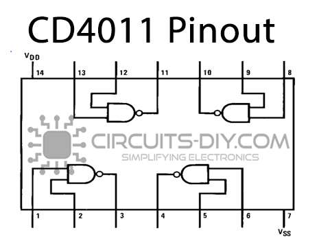
For a detailed description of pinout, dimension features, and specifications download the datasheet of CD4011BE
Electric Field Detector Circuit
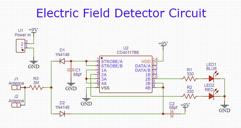
Working Explanation
The working of this circuit is pretty simple when the sensor antenna is brought close to any static electricity field, the coil energizes & sends -ve charges from the cathode of the first diode and +ve charges from the anode of the second diode. The diode output then moves on towards the input terminals of the IC.
To indicate the presence of -ve & +ve charges through the blue LED the two strobe inputs (A & B) are shorted. The resultant output from the IC triggers the Red or Blue LED depending upon the charge polarity.
Application
- Generally used as a safety feature for devices such as AC/DC Motors, Generators & transformers, etc.