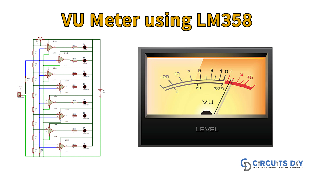
We will create an excellent entertaining simple VU meter circuit using the LM358 demonstration. Furthermore, the VU Meter or Volume Meter is a ubiquitous and enjoyable electronics project. In harmonic systems, we should consider the volume meter as an equalizer.
If music is loud and annoying, then the equalizer goes towards the peaking of LEDs, and more LEDs are flashing, and if it sic is small, fewer LEDs will sparkle. Volume measurement (VU) is a sound intensity indicator or reflection over LEDs that can also be used as a volume reference method.
Hardware Component
The following components are required to make VU Meter Circuit
| S.no | Component | Value | Qty |
|---|---|---|---|
| 1. | IC | LM358 | 4 |
| 2. | Power Supply | – | 1 |
| 3. | AUX cable | – | 1 |
| 4. | Breadboard | – | 1 |
| 5. | LED | – | 8 |
| 6. | Music Source (Mobile or Laptop) | – | 1 |
| 7. | Connecting wires | – | – |
| 8. | Audio Jack | 3.5 mm | 1 |
| 9. | Resistor | 10k, 1k | 2, 16 |
| 10. | Variable resistor | 100k | 1 |
LM358 Pinout

For a detailed description of pinout, dimension features, and specifications download the datasheet of LM358
VU Meter Circuit
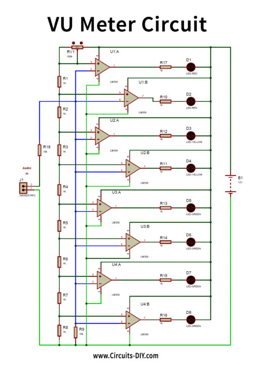
Circuit Operation
We use 8 LEDs in this VU meter circuit in which 2 red LEDs are being used to signal the highest audio graph, 2 red LEDs are used to signal the moderate audio, and 4 green LEDs are used to signal the lowest audio. The 8 circuits present on four LM358 ICs are attached to all LEDs at maximum output. Developers will decrease the cost of resistors (1k) connected with LEDs for driving highly bright LEDs.
We also use LM358 op-amps in the entire VU meter as a comparator and 1K resistivity & 100K pot as resistance divider in the non-inverting terminals to monitor and control the connection voltages (+) of both comparators.
Applications and Uses
VU meters are used when audio adjustments must be detected. The sound noise level can change even in the slightest.