In this tutorial, we are going to make and understand “Passive Filter Circuits”.
Filters are circuits that can pass a particular frequency band through it while rejecting the other frequencies outside the band. Filter circuits basically exhibit the property of frequency selectivity. Passive filters are the filter circuits that are formed using only resistor, inductor, and capacitor as their major components, to generate a signal of a particular band. And no external source is needed in passive filters.
As no amplifying element is present in it thus passive filters offer low signal gain. This leads to the reception of the comparatively low signal at the output of the filter circuit than the applied input signal. For radio-frequency range, passive filters offer a good response. But the presence of an inductor in the circuit creates problems in low-frequency applications. As in the case of low frequencies, the inductance of the inductor must be increased, which ultimately needs more turns in the coil. we can make the following filters.
- Low Pass Filter
- High Pass Filter
- Band Pass Filter
The input signal to the circuit may have a different level of frequency, here we can fix lower cutoff frequency (FL) or Higher cutoff frequency (FH) and allow or stop a particular frequency signal to the circuit.
Low Pass Filter(RC)
Two passive components simple Resistor and capacitor across the input signal can form the low pass filter circuit.
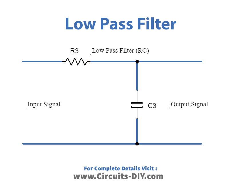
A Low Pass Filter is a circuit that can be designed to modify, reshape or reject all unwanted high frequencies of an electrical signal and accept or pass only those signals wanted by the designer, it allows the input signal frequency below the lower cutoff frequency level from 0Hz to its cut-off frequency, Fc point to pass while blocking those any higher. By changing the value of the Resistor and capacitor we can change the cutoff frequency level.
Fc = 1/ 2 (π)RC
Fc = Cutoff frequency
R = Resistor
C = Capacitor
High Pass Filter(RC)
By using a simple Resistor and Capacitor we can design a high pass filter circuit.
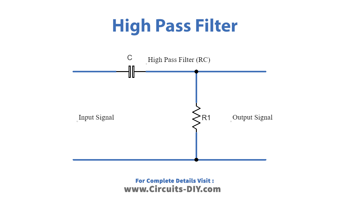
A High Pass Filter is the exact opposite to the low pass filter circuit as the two components have been interchanged with the filter’s output signal now being taken from across the resistor. High pass filter formed by connecting capacitor series to the input signal and connecting resistor parallel to the input signal. the passive high pass filter circuit as its name implies, only passes signals above the selected cut-off point, Fc eliminating any low-frequency signals from the waveform.
Fc = 1/ 2 (π)RC
Here Fc represents cutoff frequency and all the input signals above the cutoff frequency allowed through this filter.
Band Pass Filter(RC)
This passive band-pass filter is designed to allow a particular frequency signal and to stop the remaining signal.
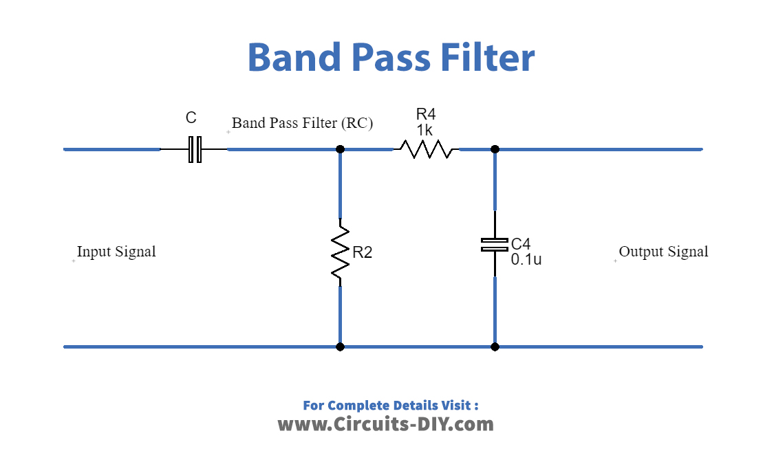
Passive Band Pass Filters can be made by connecting together a low pass filter with a high pass filter. Band Pass Filters can be used to isolate or filter out certain frequencies that lie within a particular band or range of frequencies. The cut-off frequency or Fc point in a simple RC passive filter can be accurately controlled using just a single resistor in series with a non-polarized capacitor. Here we need to carefully calculate lower cutoff frequency and higher cutoff frequency.
FLC = 1/ 2 (π)R2C2
FHC = 1/ 2 (π)R1C1
FLC= Lower cutoff frequency
FHC= Higher cutoff frequency
Above three passive filters are designed by using Resistor and capacitor elements, we can also design the same by using Resistor and Inductor elements.
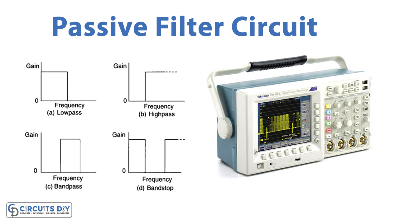
Ideal Filter Response
This diagram clearly shows the Ideal response of frequency and amplitude level of output signals for low pass, high pass, and bandpass filters.