Introduction
The world of electronics is a vast and exciting realm filled with countless opportunities for exploration and experimentation. And what better way to dive into this fascinating field than by building your radio circuit? With just a few basic components and simple instructions, you can create a device that will allow you to tune in to powerful radio signals from across the airwaves.
But this is no ordinary radio circuit. No, this creation will leave your friends and family in awe of your technical prowess and creativity. With the ability to pick up a wide range of frequencies using a 10-foot antenna and a crystal radio with an audio amplifier, you can tune in to all your favorite stations and enjoy the crisp, clear sound quality. So what are you waiting for? Let’s get started on building your very own radio circuit and unlock the power of the airwaves!
Hardware Required
| S.no | Components | Value | Qty |
|---|---|---|---|
| 1 | IC | LM358 | 1 |
| 2 | Capacitor | 100, 330nF | 3 |
| 3 | Resistor | 10k, 1M, 100K, 470 | 2, 2, 2, 1 |
| 4 | Diode | OA91 | 1 |
| 5 | Polar Capacitor | 100uF | 1 |
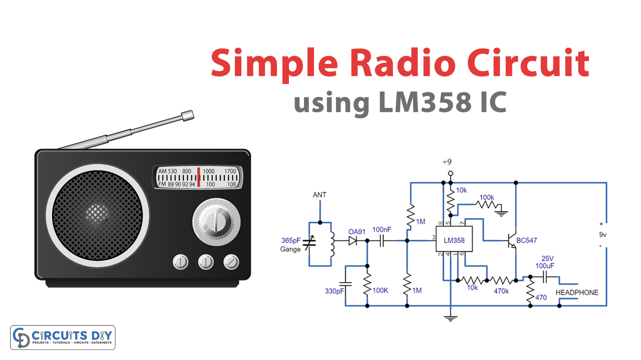
Circuit Diagram
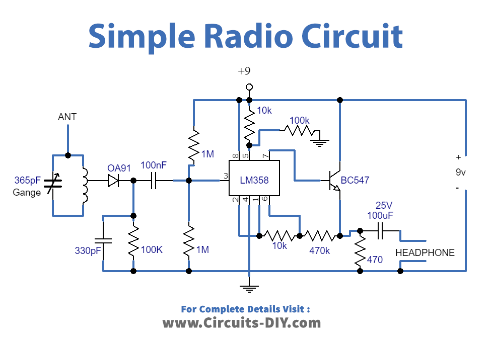
Circuit Explanation
This radio circuit receives several powerful programs in a given area using a 10-foot antenna. With a longer antenna, the reception could be stronger, but the selectivity could be compromised. Here’s the explanation of circuits:
Inductor
The inductor of the circuit should be wound using 200 turns of 28SWG enameled copper wire over a 7/8 diameter, 4-inch-long PVC pipe. This could create around 220 uH value for the inductor. The inductor could be wound with terminals after every 20 spins, making 60 turns through the antenna ending with the diode.
Diode
The diode could be germanium for optimal results, but silicon diodes could perform if the transmission is powerful. The carrier frequency is stripped away from the rectified signal with the cathode of the diode through the 300 pF cap.
Op-Amp
The audio frequency is flushed with the 0.1uF capacitor into the non-inverting input of the relevant op-amp, which acts like a high-impedance buffer stage. The other op-amp stage improves the voltage level approximately 50 times and is coupled to the previous one via the 10K resistor.
Gain Limiting
If the units of 100K and 1 Meg resistors are dissimilar in value (1%), it might be necessary to use better equivalent values or add a capacitor in line with the 10K resistor to keep the DC voltage within the transistor emitter between 3 and 6 volts. Another strategy involves limiting the overall gain using a smaller feedback resistor (470K).
Earphones
High-impedance earphones will provide an improved listening experience, but stereotypical headphones will also work. The proposed simple radio circuit works with approximately 10 mA from a 9-volt battery.