Introduction
To sense the movement and position of an object in a system, a sensor known as the hall effect is used. The Hall Effect Sensor is a solid-state device that becomes active when exposed to a magnetic field. The magnetic field around a hall effect sensor affects its output voltage. The magnetic flux density changes as the magnetic field across the semiconductor slab changes, causing the output voltage of the Hall effect sensor to shift. So, in this tutorial, we are going to make the “Multipurpose Hall Effect Sensor Circuit”.
In the making of this circuit, we are using DRV5013 IC. The DRV5013 is Hall effect sensor IC that provides a magnetic sensing solution with excellent temperature sensitivity stability and built-in protective features. This IC is suited for a wide variety of engineering applications because of its wide working voltage range of 2.5 V to 38 V and reverse polarity protection up to –22 V.
This hall effect sensor has just three pins and is tiny enough to be used in the design of hand-held electric tools, power tools, tachometers, valves, and solenoids, among other things.
Hardware Components
The following components are required to make Hall Effect Sensor Circuit
| S.no | Component | Value | Qty |
|---|---|---|---|
| 1. | Transistor | BC547 | 2 |
| 2. | Relay | – | 1 |
| 3. | IC | DRV5013 | 1 |
| 4. | Diode | 1N4007 | 1 |
| 5. | LED | – | 1 |
| 6. | Capacitor | 0.01uf | 1 |
| 7. | Resistor | 3KΩ, 10KΩ, 100Ω, 447Ω | 1,1,1,1 |
| 8. | Connector | 2-Pin | 1 |
DRV5013 Pinout

For a detailed description of pinout, dimension features, and specifications download the datasheet of DRV5013
Hall Effect Sensor Circuit
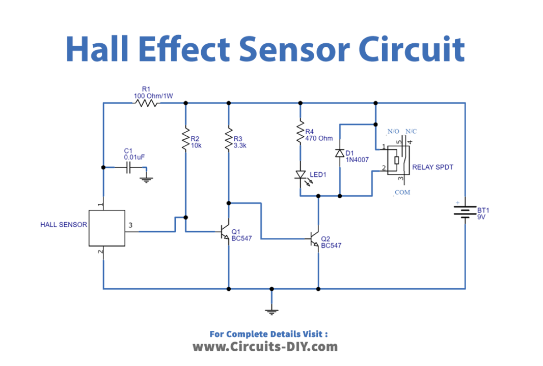
Working Explanation
An SPDT Relay is wired at the output stage of the hall sensor in this multipurpose Hall Effect Sensor Circuit, allowing any load to be controlled based on the sensor output. When the south pole of the magnet approaches close to the DRV5013, the output drops, causing the transistor Q1 to open, allowing the positive supply to reach the base of transistor Q2 with the help of the R3 resistor. When the base bias appears, the Q2 transistor closes. The relay and LED then get power and enter the turn-on state.
Application and Uses
- Tachometers.
- Power tools.
- Brushless DC motors.
- Flow meters, etc