In this tutorial, we are going to make a “Heat Sensor Circuit”.
Nowadays it is essential to install heat sensor circuits in industries, shopping malls, and residential areas to prevent anything from fire accidents and improve the security system. The usage of heat sensor circuit is inside your PC or in your kitchen. Due to overheating, the expensive components present in the PC or kitchen appliances could be damaged. When the temperature around the heat sensor increases above its set value, then it senses the heat and gives an indication, so that we can protect the devices from damage. We design a simple heat sensor circuit to give an alert sound when the temperature reaches the desired threshold.
This circuit utilizes NTC (Negative Temperature Coefficient) thermistor hence the resistance value of this device decreases when the temperature rises. Here we can adjust the temperature threshold level using variable resistor RV1. This simple circuit is easy to construct and test.
Hardware Components
The following components are required to make Heat Sensor Circuit
| S.no | Component | Value | Qty |
|---|---|---|---|
| 1. | NTC thermistor | 2.2KΩ | 1 |
| 2. | Variable Resistor | 10KΩ | 1 |
| 3. | Transistor | BC547 | 1 |
| 4. | Buzzer | 9V | 1 |
| 5. | Capacitor | 1uF/16V | 1 |
| 6. | Connecting Wires | – | 1 |
| 7. | Battery | 9V | 1 |
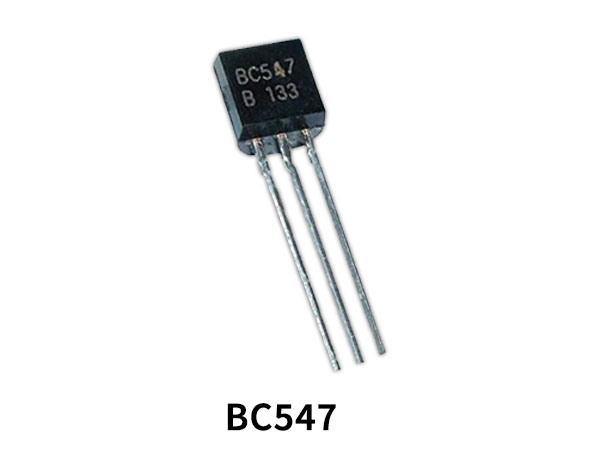
BC547 Pinout

For a detailed description of pinout, dimension features, and specifications download the datasheet of BC547
Heat Sensor Circuit
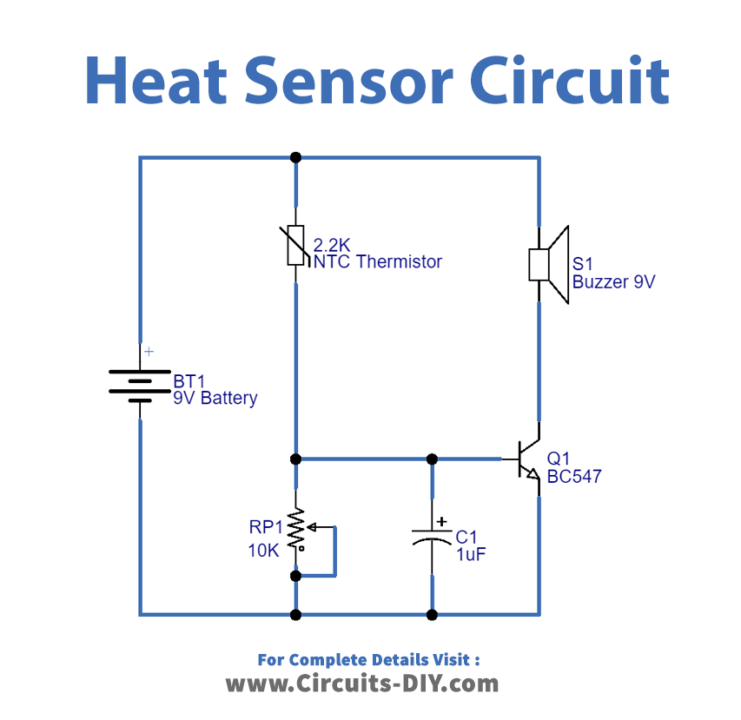
Working Explanation
The simple heat sensor circuit is shown below. An NPN transistor BC547, a thermistor (2.2K), and other a few components are used in a heat sensor. In this circuit, the transistor acts as a switch and it turns ON the buzzer when the temperature rises over the threshold and turns OFF the buzzer when the temperature is below the threshold. The NTC thermistor 2.2K is connected with the variable resistor and base terminal of transistor Q1. Hence the base of Q1 gets biased through thermistor and variable resistor. Here RV1 resistance value decides the temperature threshold. Buzzer element is connected with battery and transistor collector terminal.
The thermistor is of negative temperature coefficient type, so after heating the thermistor, the resistance decreases and excess current flows through the thermistor. As a result, more amount of voltage is found at the thermistor. This voltage is applied to an NPN transistor as the resistance value of TH1 gets decreases and allows bias from the battery to the base terminal of the transistor, then the transistor gets turned ON and makes the buzzer sound. If there is no rise in temperature then the TH1 thermistor gives full resistance to the bias from the battery to the base terminal of the transistor and turns OFF the buzzer.
Applications
The heat sensor circuit senses the heat from various electronic devices like amplifiers and computers thus generating the warning alarm.
Can be used in industries, shopping malls, and residential areas.