Introduction
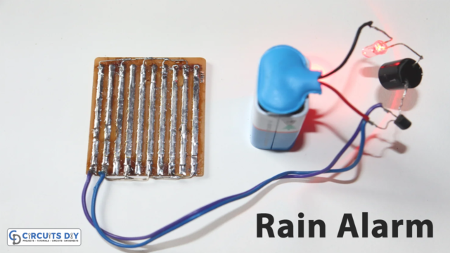
In our surroundings, where we work, and where we live, many different parameters can cause alarming situations. For example, a fire that can occur, an intruder that comes, or any other thing that needs the alarm. So, multitone alarms help to identify the arising situation. Different tones of alarms can be set for different purposes to understand the situation. And, for this reason, in this tutorial, we are going to “Configurable alarm with Multitone”.
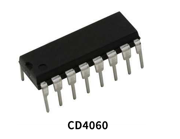
The circuit is using CD4060 IC, The CD4060 is a 14-stage counter IC with a binary ripple-carry counter. It’s a binary counter using CMOS circuitry that’s part of the CD4000 line of integrated circuits. A counter and an internal oscillator make up the circuit. We may also use RC circuits or an external crystal to configure crystal oscillators. It also has a reset circuit that allows the counter to be reset to zero. It works with a power supply ranging from 3 to 15 volts.
Hardware Components
The following components are required to make a Configurable Alarm Circuit
| S.no | Component | Value | Qty |
|---|---|---|---|
| 1. | IC | CD4060 | 1 |
| 2. | Thermistor NTC | 100KΩ | 1 |
| 3. | Loudspeaker | 8Ω | 1,1 |
| 4. | LED | – | 2 |
| 5. | Switch | – | 1 |
| 6. | Transistor | BC337 | 2 |
| 7. | Transistor | BD139 | 1 |
| 8. | Variable resistor | 22KΩ, 100KΩ | 1,1 |
| 9. | Ceramic capacitor | 0.33uF, 100pF, 10nF, 120pF, 100uF/10V | 2,1,1,1,1 |
| 10. | Resistor | 1KΩ, 10kΩ, 220kΩ, 10kΩ, 5.6kΩ, 10Ω | 3,2,1,1,1,1 |
CD4060 Pinout

For a detailed description of pinout, dimension features, and specifications download the datasheet of CD4060
Configurable Alarm Circuit

Working Explanation
CD4060 (IC1) is a CMOS IC that includes three oscillator terminals, ten counter buffered outputs, and an active ‘high’ master reset. It is used in this Configurable alarm with Multitone to simultaneously generate 10 distinct square waves. Using switches, from S1 to S10 these square waves may be blended to generate various output tones.
The frequency of the oscillator is mostly determined by the values of components C4, R4, R15, and VR2. The frequency of the oscillator can be adjusted using the potentiometer VR2 if necessary. When many alarms are used near each other, trimming is effective for obtaining distinct clock frequencies. VR1 can be substituted with a fixed-value resistor if trimming is not required.
Application and Uses
- In offices, industries, and other places.
- In safety devices.
- Different monitoring systems.