Introduction
Horns need no introduction. If you live in a busy city, having loads of road traffic, you might get irritated by horns. But, what if we change that irritation into education? Are you ready? Because, in this tutorial, we are going to “Electronic horn circuit”. This easy circuit uses two IC555 timers to create a louder horn for vehicles or alarms. The output sound is created through loudspeakers.
The 555 integrated circuit (IC) is a very stable device for creating precise time delays and oscillation. If required, additional terminals are supplied for triggering or resetting. One external resistor and capacitor accurately regulate the time in the time delay mode of operation.

Hardware Components
The following components are required to make Electronic Horn Circuit
| S.no | Component | Value | Qty |
|---|---|---|---|
| 1. | IC | NE555 Timer | 2 |
| 2. | Speaker | 8Ω | 1 |
| 3. | Potentiometer | 1MΩ | 2 |
| 4. | Electrolytic Capacitor | 10uF | 1 |
| 5. | Ceramic Capacitor | 0.1nF | 1,1 |
| 6. | Resistor | 10KΩ, 200KΩ | 1,1 |
| 7. | Battery | 9v | 1 |
| 8. | Connector | 2-Pin | 2 |
555 IC Pinout

For a detailed description of pinout, dimension features, and specifications download the datasheet of 555 Timer
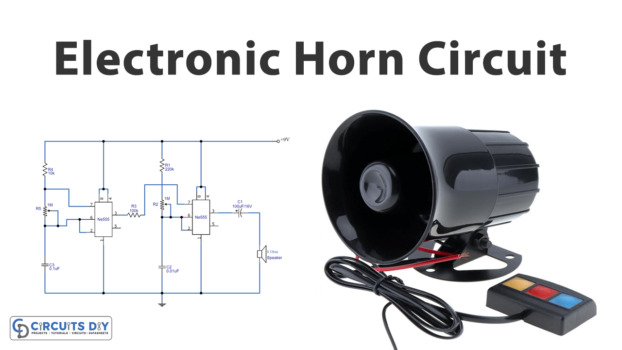
Electronic Horn Circuit
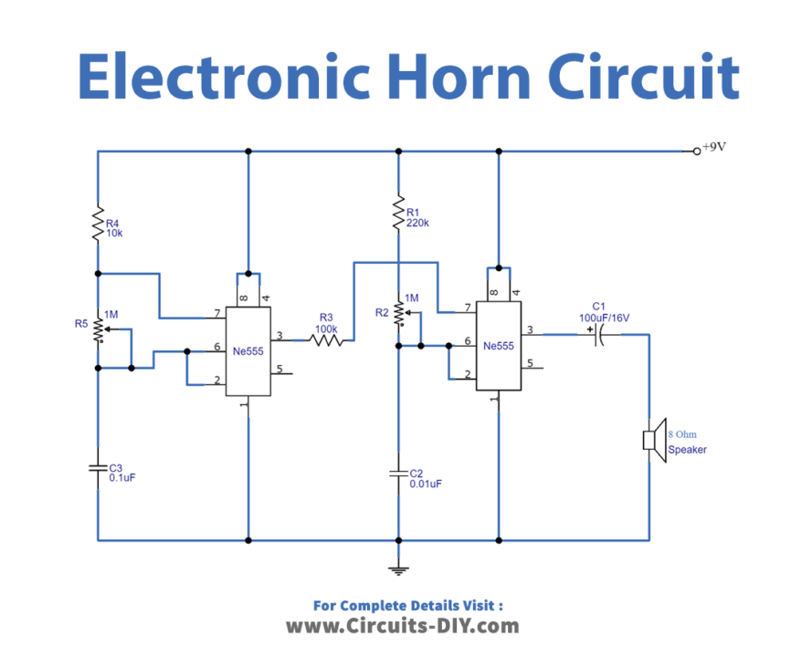
Working Explanation
In this Electronic horn circuit, we are using two 555 timers ICs. The first IC generates pulse output when we supply the power through 9 volts of battery. The output of that first is then provided to the second IC, The second 555 timer IC generates the high-frequency pulse and becomes the input for the loudspeaker. Resistor r$, and potentiometer R5 work as the timing resistors for the first 555 timer IC. Hence, you can change the pulse duration of the respective IC by adjusting the potentiometer.
Application and Uses
- The circuit can be utilized in different alarm circuits.
- The circuit can have good use in the automotive industry. For example, it can be used in vehicles, etc.