Depending on the circuit, the frequency and amplitude can differ. Many kinds of waveforms are observed, such as sine waves, triangular waves, square waves, ramps, sawteeth, etc. The sine wave and square wave generator circuits have already been developed in our previous circuits. In this DIY tutorial, we will teach you how to prototype an adjustable gain and DC offset sawtooth wave generator circuit using Op-amp and a NE555 timer IC.
A waveform from Sawtooth has a non-sinusoidal shape, like a triangular waveform. It is called a sawtooth since it looks much like a saw’s teeth. The sawtooth pattern is different from the triangular wave pattern of the wave since a three-way wave has the same back and forth cycle, and a sawtooth wave pattern increases from zero to its highest value and then rapidly decreases to null.
Hardware Components
The following components are required to make Sawtooth Waveform Generator Circuit
| S.no | Component | Value | Qty |
|---|---|---|---|
| 1. | IC | NE555 Timer | 1 |
| 2. | Op-amp IC | LM358 | 1 |
| 3. | Oscilloscope | – | 1 |
| 4. | Transistor | BC557 | 1 |
| 5. | Potentiometer | 10k | 2 |
| 6. | Resistor | 4.7k, 10k, 22k, 100k | 1,3,3,3 |
| 7. | Ceramic Capacitor | 0.1uf, 1uf, 4.7uf, 10uf | 1,1,1,1 |
| 8. | Battery | 9V | 1 |
| 9. | Breadboard | – | 1 |
| 10. | Jumping Wires | – | 1 |
NE555 IC Pinout

For a detailed description of pinout, dimension features, and specifications download the datasheet of NE555 IC
LM358 Pinout

For a detailed description of pinout, dimension features, and specifications download the datasheet of LM358
Sawtooth Waveform Generator Circuit
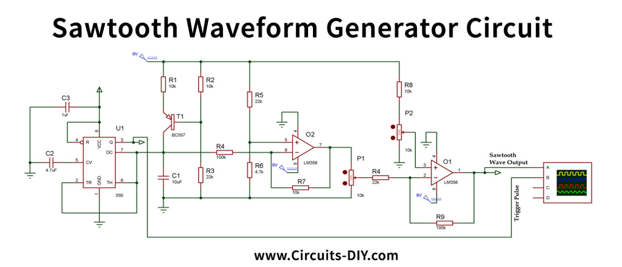
Working Explanation
We have utilized the NE555 IC and LM358 Dual Op-amp IC for producing the sawtooth waveform. In this circuit, we are using T1 as a regulated current source with an appropriate emitter and the current collector. In astable mode, here, the 555 Timer IC is being used.
The R2 and R3 resistors set the Bias voltage for the PNP Transistor T1 base pin bias. And R1 is being used to set the emitter current that essentially sets the collector current and linearly charges the condenser C1 with this constant current. This is how the performance of the ramp is obtained. You can change the ramp speed by substituting R1 with a potentiometer.
It enables the capacitor to discharge and charge by chopping the trigger, connect the threshold pin of the 555 timer IC straight with the capacitor C1.
Here the first O1 acts as a buffer to move the stage. The bottom half of the ramp becomes the top part of the inverted ramp since it is an inverting buffer.
This op-amp’s output is then added to the POT P1 to change the pulse amplitude. Op-amp O2 is often used to adjust the DC signal offset. And the readings are taken from the Op-amp O2 output terminal.
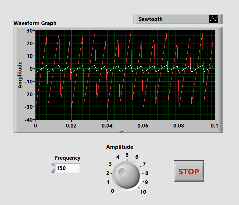
Below is an example of a perfect sawtooth waveform:

Applications and Uses
The waveform of Sawtooth is used in sensors and amplifier circuits. It is also used for toning, modulation, filtering, and so forth.