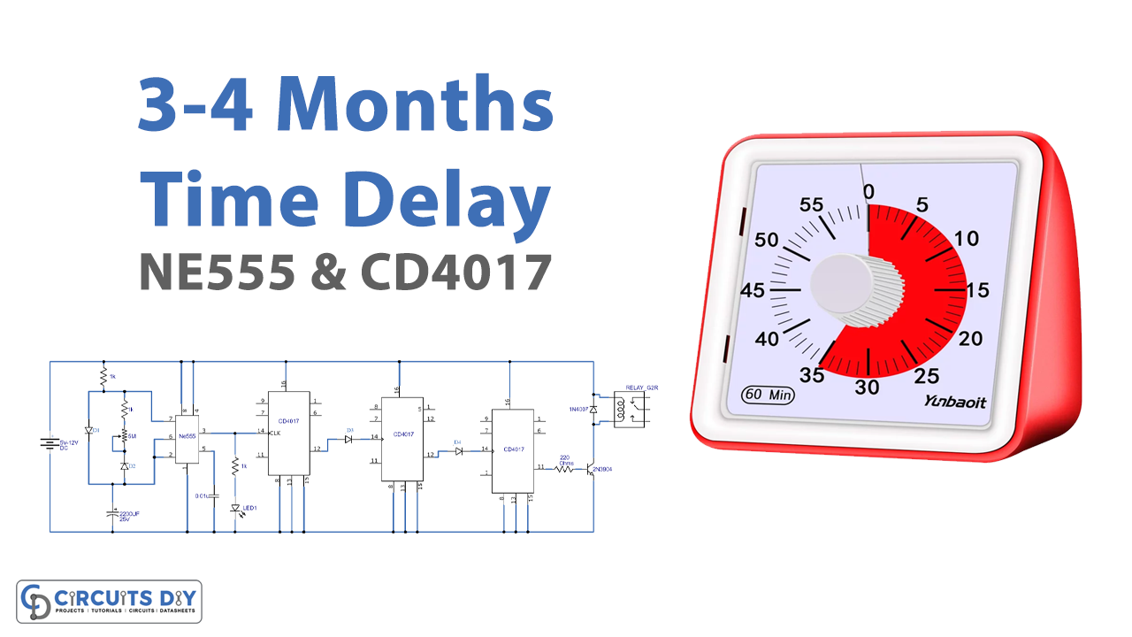
This is a circuit of a Three To Four Months Duration Timer which can be adjusted from a few minutes to several months (up to four months). We are using four ICs (one of them is a 555 timer and the other three are decade counters), a transistor, and some other discrete components.
You don’t have to wait too long to calibrate the circuit. You just have to calibrate the output pulse of the 555 timer IC through some calculations which we have shown later in this tutorial. Through these calculations, you can set the desired time duration of months, weeks, days, or minutes.
Hardware Components
The following components are required to make the Duration Timer Circuit
| S.no | Components | Value | Qty |
|---|---|---|---|
| 1. | Battery | 5-12V | 1 |
| 2. | IC | NE555 Timer | 1 |
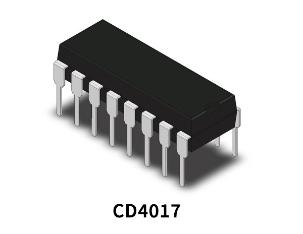
| 3. | Decade Counter IC | CD4017 | 1 |
| 4. | Diodes | 1N4148 | 1 |
| 5. | Transistor | 2N3904 | 1 |
| 6. | LED | – | 1 |
| 7. | Resistor | 1KΩ, 220Ω | 3, 1 |
| 8. | Electrolytic Capacitor | 2200µF | 1 |
| 9. | Ceramic Capacitor | 0.01µF | 1 |
| 10. | Relay | 12V | 1 |
CD4017 Pinout
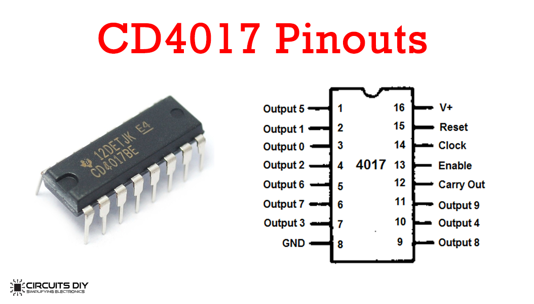
For a detailed description of pinout, dimension features, and specifications download the datasheet of CD4017
NE555 IC Pinout

For a detailed description of pinout, dimension features, and specifications download the datasheet of 555 Timer
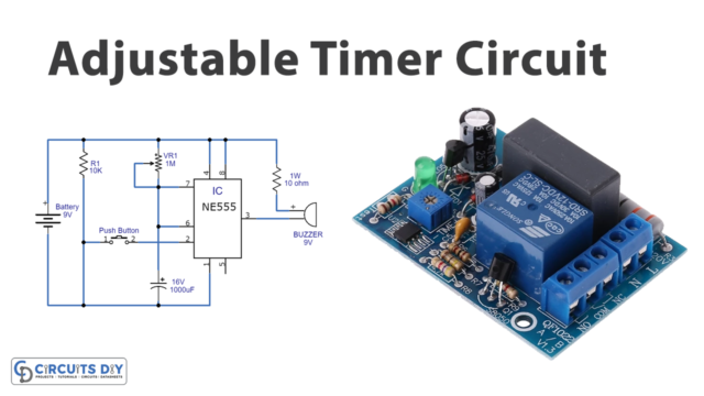
Duration Timer Circuit
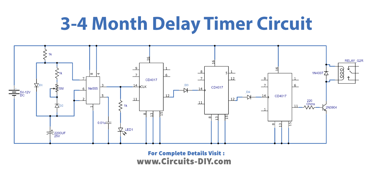
Working Explanation
The operating voltage of this circuit is 5-12 volts. IC1 is a 555 timer which is generating clock pulses on the input of the decade counter IC2. The frequency of these clock pulses can be adjusted through a 5M variable resistor. We have connected an LED at the output of IC1 to indicate its pulses. These ICs are connected in such a way that the output of one IC becomes the input of the IC next to it. IC4 is providing the final output which activates the relay with the help of a transistor. To drive any AC/DC load just connect it with the relay.
You can also use a piezo buzzer between pin 3 and ground of 555 timer for a sound indication of the output pulse. LED, piezo buzzer and the 1K resistor used in the series with LED can be removed from this circuit after its calibration
Circuit Calibration
Before calibration, test the circuit if it’s working properly. It can be done by setting the resistance of the variable resistor to its minimum by using a 10uF capacitor in the place of a 2200uF capacitor. By doing this the LED will blink very fast switching the relay after a few seconds indicating that the circuit is working properly.
To calibrate this circuit, adjust the variable resistor to adjust the output pulse of 555 timer. If you have adjusted it to generate a pulse in the gap of 3 and a half hours then the calculation will be,
3.5 x 10 x 10 x 10 = 3500 / 24 = 145.8
This calculation shows that the total timer duration of this circuit will be around 145-146 days. This can be increased by changing the 2200uF capacitor with a higher value capacitor (3300uF or more)