Break failures have become a very common problem nowadays due to the increase in the number of automobiles. We depend on automobiles for our day-to-day commute. Although it is very hard to avoid an accident in case of brake failure. But if we get an early indication regarding brake failure then we can take precautionary measures to reduce the amount of damage that can result from an accident.
In this project, we are going to show you how to make a Break Failure Indicator Circuit using 555 Timer IC. This circuit can be attached to a vehicle and it will monitor the brakes of the vehicle. In case of any brake failure, it will provide us with audio-visual feedback.

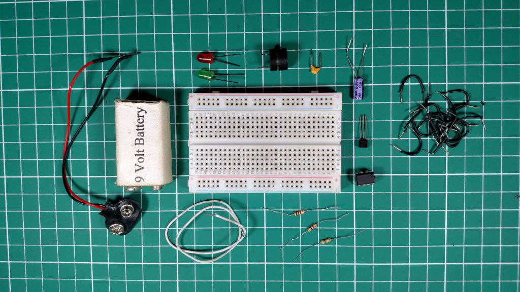
Hardware Components
The following components are required to make Brake Failure Indicator Circuit
| S. NO | Component | Value | Qty |
|---|---|---|---|
| 1. | Breadboard | – | 1 |
| 2. | Battery | 9v | 1 |
| 3. | Connecting Wires | – | 1 |
| 4. | IC | NE555 Timer | 1 |
| 5. | PNP Transistor | BC557 | 1 |
| 6. | Resistor | 470K, 1K, 220 ohm | 1,1,1 |
| 7. | Ceramic Capacitor | 0.1uF | 1 |
| 8. | Electrolytic Capacitor | 1uF | 1 |
| 9. | LED | 5mm | 2 |
555 IC Pinout

For a detailed description of pinout, dimension features, and specifications download the datasheet of 555 Timer
Circuit Diagram
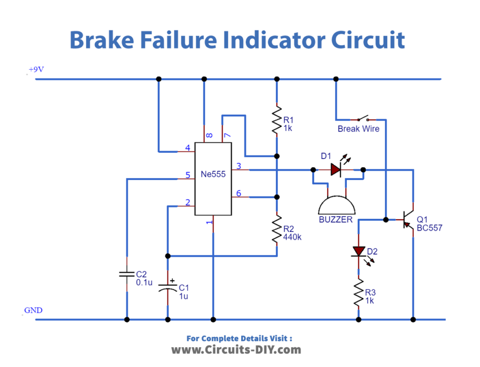
Connections
- Connect Pin 4 and Pin 8 To VCC.
- Use a jumper wire to connect Pin 6 and Pin 2 together.
- Use a jumper wire to connect Pin 1 to GND.
- Connect the 1uF capacitor between Pin 2 and GND.
- Connect the 0.1uF capacitor between Pin 5 and GND.
- Add Red LED & Buzzer in parallel between Pin 3 and Collector of Transistor.
- Connect the R1 Resistor between Pin 7 and VCC.
- Connect the R2 Resistor between Pin 6 and Pin 7.
- Add Green LED to the Base of the transistor with a resistor.
- Connect the Emitter of the Transistor to the GND.
- Insert the Brake wire between the Base of the transistor and the VCC.
Working Explanation
In this circuit, we will operate a 555 timer in astable mode. The On/Off time of the pulse produced can be varied by changing the value of resistors (R1 & R2) and capacitor C1. To control the buzzer and LEDs we have used a PNP-type transistor (BC557). The base of this transistor is connected to the VCC when the brake wire is in proper condition. This only drives the Red LED while the buzzer and Green LED will remain Off. When we cut the brake wire, the transistor will get disconnected and the Red LED will turn Off. Now, the buzzer and Green LED are connected to the ground hence they will turn On. The buzzer and LED will start beeping and blinking depending on the time duration set by the RC network.
Applications
- This circuit can be used in mechanical cranes to warn people standing near the crane, in case of an emergency.
- When used in cars, this circuit can notify the driver and surrounding traffic in case of brake failure.