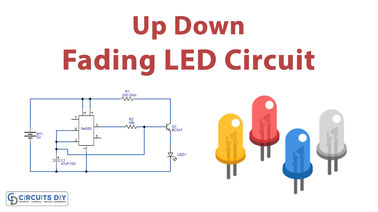
In this tutorial, we are going to make a “Simple Up/Down Fading LED Circuit”.
As we have seen LEDs glowing and fading (where the LED lights increase and decrease their intensity depending on the number of persons entering or leaving a particular place or a room) in LED strip lights, used for decoration in festivals and functions. Because the usage of LED lights is increasing rapidly due to their reduced cost and long durability of course their low power consumption. Therefore, we don’t need an expensive PWM circuit or driver IC to produce fading light. Here we design a simple Up/Down fading LED circuit with timer IC 555 and a few easily available components to produce a breathing light effect through the LED. In this circuit we tested a single LED, you can connect up to three LEDs. This simple circuit is enough to give fading LED effect, make sure to apply proper bias.

Hardware Components
The following components are required to make Fading LED Circuit
| S.no | Component | Value | Qty |
|---|---|---|---|
| 1. | Transistor | BC547 | 1 |
| 2. | IC | NE555 Timer | 1 |
| 3. | Resistor | 330Ω, 68KΩ | 1,1 |
| 4. | Capacitor | 47μF/16V | 1 |
| 5. | LED | – | 1 |
| 6. | Connecting Wires | – | – |
| 7. | Battery | 9V | 1 |
555 IC Pinout

For a detailed description of pinout, dimension features, and specifications download the datasheet of 555 Timer
BC547 Pinout

For a detailed description of pinout, dimension features, and specifications download the datasheet of BC547
Fading LED Circuit
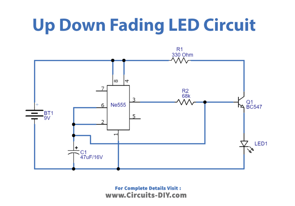
Working Explanation
The main part of this circuit is IC 555, which acts as an astable multivibrator. It produces a continuous timing pulse (oscillating at a particular frequency depending on RC components means output at PIN 3 goes HIGH and LOW periodically); here output pulse is connected to the timing capacitor C1 through the R2 resistor. Threshold and trigger pins are also connected with timing capacitor C1. Target LED is connected to the Q1 transistor emitter and this transistor collector terminal is connected to the battery through the R1 resistor. Output from timer IC is applied to the Q1 base through the R2 resistor.
When the circuit is powered through a 9V battery, the IC 555 starts to oscillate the square pulse depending on the timing resistor and capacitor. But here we provide only capacitor C1 to the timer IC and also it can be charged through only the output signal. Now initially output of the timer is high so the transistor turns ON and makes the LED glow, during that time slowly C1 capacitor gets charged (up to 2/3 Vcc) and makes the timer output low and the Q1 transistor becomes saturation but the capacitor charge slowly gets discharge through transistor Q1(collector-emitter junction) to LED so the LED glows brightly to dimmer level, this process occurs continuously up to the presence of power supply to this circuit.
Applications
- This can be used in shopping malls for fading out the lights in places where there is no crowd.
- Fading LEDs can be used in security applications to alert something.
- These can be used in home applications.