The transistor is the most often failed part of electronics. Testing must be carried out by a multimeter to verify the functioning of the transistor. This takes a lot of time by checking one terminal after another, and it isn’t a good choice for newbies.
The transistor test circuits are difficult to understand. In this tutorial, a basic 555 TIMER circuit will be built to measure the transistor’s functionality in seconds. This circuit is an easy way to track the functioning of a newbies transistor.
Hardware Component
The following components are required to make Transistor Tester Circuit
| S.no | Component | Value | Qty |
|---|---|---|---|
| 1. | IC | NE555 timer | 1 |
| 2. | Supply voltage | 9V | 1 |
| 3. | Resistor | 1KΩ, 100Ω | 2, 1 |
| 5. | Variable Resistor | 100K | 1 |
| 6. | Electrolyte Capacitor | 100µF | 1 |
| 7. | LED | – | 1 |
| 8. | Transistor | – | 1 |
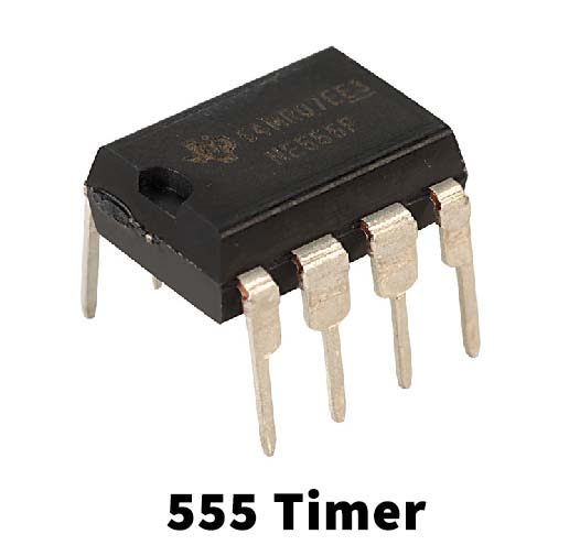
NE555 IC Pinout

For a detailed description of pinout, dimension features, and specifications download the datasheet of 555 Timer
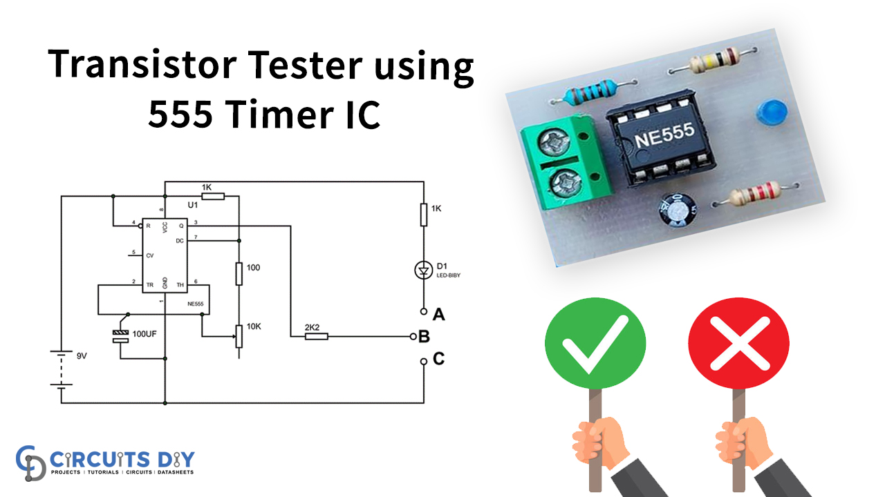
Transistor Tester Circuit
Working Explanation
This figure displays the circuit diagram of TRANSISTOR TESTER. The timer functionality is to act as a transistor square wave generator. This clock is attached to the base of the transistor.
The circuit above has current resistors; this means that we would not have trouble with a failed transistor’s short circuit current. Thus the circuit can effectively evaluate any transistor.
During communication, certain transistors have protection diodes that allow the LED to turn on, resulting in an incorrect conclusion continually.
A 10uF one can replace the circuit capacitor for a higher blinking frequency.
Applications and Uses
A transistor tester is a device used the checking a transistor or diode’s electrical behavior.