Introduction
Do you want to discover the magic behind how a simple device can tune in to broadcasts from faraway places? Then get ready to dive into the fascinating short-wave radio circuits world!
In this blog post, we will deeply dive into the workings of a short-wave radio circuit. We will explore the various components of the circuit and how they work together to pick up radio signals and convert them into sound. So sit back, grab your components, and get ready to discover the magic of short-wave radio!
Hardware Required
| S no | Components | Value | Qty |
|---|---|---|---|
| 1 | IC | LM386N | 1 |
| 2 | Transistor | BF494, BF256C, BF557B, | 2, 2, 1 |
| 3 | Resistor | 120K, 100N, 470K, 5K6, 10N, 47K, 6K8, | 1, 1, 1, 4, 1, 1, 1 |
| 4 | V. Resistor | 1K, 100K, 10K, | 2, 1, 1 |
| 5 | Polar Capacitor | 1u, 4u7, 10u, 100u, 470u | 1, 1, 1, 1, 1 |
| 6 | Non Polar Capacitor | 47n, 330n, 10n, 1n, 100n, 100p, 58n, | 1, 1, 3, 1, 1, 1, 1 |
| 7 | V. Capacitor | 500p | 1 |
| 8 | Diode | AA119 | 1 |
| 9 | Speaker | 8ohm | 1 |
Circuit Diagram
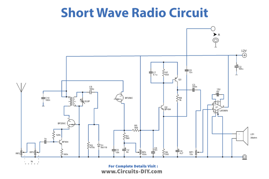
Working Explanation
A short-wave radio receiver is a device that allows you to listen to radio broadcasts from faraway places. Usually, you tune to a specific frequency, and the radio picks up the signal from the antenna and converts it into sound.
But there is another way to use the radio called “oscillating mode.” This mode allows the owner to use various product-detector reception modes like CW, RTTY, and SSB. Adding a frequency counter can make this feature even better.
To use this mode, a bipolar transistor and a FET connected in series are added to the RF stage of the circuit. This helps to minimize pulling and keep the input aperiodic.
One disadvantage of the radio is that it can get overloaded with too much input. However, the high sensitivity of the radio compensates for this. Even a tiny whip antenna can be enough. To counteract regeneration, the transconductance is lowered.
To do this, the process starts with D1 helping to control regeneration. When the threshold voltage is reached, a negative bias is supplied for T3, which lowers its transconductance.
Another advantage of the detector used in this radio is that it can cope with relatively strong input signals. This means distortion will be low for heavily modulated (AM) carriers.
Conclusion
And there you have it – a glimpse into the fascinating world of short-wave radio circuits! This blog post has shed some light on how a simple device can tune in to broadcasts from faraway places and convert them into sound.
Try to create this circuit, and the next time you tune in to a broadcast from a faraway land, remember the circuitry behind the magic and appreciate the ingenuity of the engineers who made it all possible. Thank you for reading!